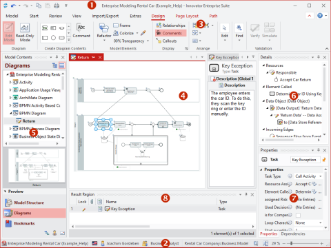
The Innovator program interface primarily consists of the ribbon, workspace and status bar. The model page shows the model in the central document area (shows diagrams, tables and specifications) and in various tool windows (Model Content, Details, Properties etc.).
-
... Elements and diagrams
-
... Diagrams only
-
... Diagrams that I can create
-
... Elements that I can create
-
... Elements that I can create in the diagram using drag-and-drop
-
... Information about a selected element
Details, Properties and Info tool windows
-
... Access rights for package levels
-
... Access rights for an element
-
... My current role and the current language
-
... Windows that I can show
Configuration of the interface and perspectives are stored for user-specific settings in the Innovator directory (INOHOME). By default, this is the %APPDATA%\Innovator\16.1\ directory. Depending on the model selected, user settings are stored in subdirectories with the respective model name.
The program interface will then be opened exactly as it was closed for the last respective model for the user for each model when starting Innovator if INOHOME is centrally set for the computer they are using.
Perspectives store configuration of the document and tool windows under a name and open this configuration again when a model is opened.
Window Components
The application window contains a central document area and various tool windows. Documents (i.e. diagrams, tables and specification texts) can only be assigned within the central document area.
Legend
(1) System menu and custom quick access toolbar
(2) Status bar with <model name> (<repository name>), model or display language, user, role, namespace of selected element and diagram zoom settings
(3) Ribbon with backstage views in the Model tab, Tabs, groups, galleries and commands
(4) Document area e.g. for diagrams, tables and specification texts as well as the Start Page
(5) Model Content tool window
(6) Details tool window
(7) Properties and Dependencies tool windows
(8) Result Region and Translation tool windows
-
System menu (1)
The system menu can be found top left in the application's window title.
-
Toolbar for quick access (1)
The toolbar for quick access can be found on the right-hand side next to the system menu as standard but can also be moved to below the ribbon. It enables individual customization of general functions which you always need to access.
-
Status bar with zoom settings (2)
You can see at a glance to the left in the status bar which model server and model you are logged-in to, with which user and with which role. The current language and - if appropriate - active change set are also displayed.
The selected element's namespace is shown in the middle.
If a diagram or diagram element is selected, handy elements for displaying diagrams are shown to the right in the status bar.
-
 icon (Entire Diagram (Ctrl+F9): the entire diagram is shown.)
 -
 icon (Original Size (Ctrl+Shift+F9): zoom to 100%.)
 - Zoom controller with percentage gage for direct zoom selection and plus and minus icons for incremental size alterations.
-
You can edit diagrams, tables and specifications etc. in the document area (4). You can add annotations to diagram elements here.
- Relationships between the model elements are modeled in the diagram editor.
- The table editor is used for quickly editing related data.
- Specification texts describe model elements within a certain aspect.
- You can use [F11] to switch between full screen mode of the document area and back at any time.
Note
The active Edit Mode pen in the diagram's icon and grid in the diagram all show that a document can be edited. Otherwise you are in read-only mode. You can change access to the document in the Design and/or Text tabs using the Edit Mode and Read-Only Mode commands.
Tool windows (5-8) provide specific structures and functions for navigating in the model, getting information about the model and its elements and so that you can work with the model elements.
Please read the following chapters for use of program interfaces:

