Icon
 The icon is of a diagram with a use case in it.
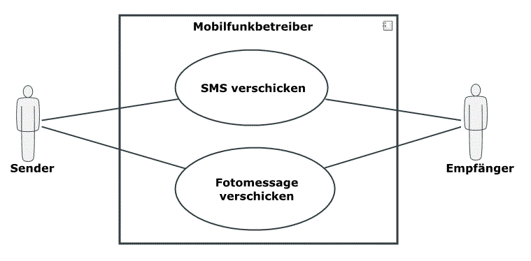
A use case diagram shows the external behavior of a system from the view of actors; it shows how actors, use cases and their relationships are related to each other.
The icon is of a diagram with a use case in it.
A use case diagram shows the relationships between actors and a set of use cases enclosed by a system limit. Depending on how the system term is interpreted, a use case diagram can be used for both business process modeling and software modeling.
Business Process Modeling
The use case diagram forms the introduction to the analysis of the business processes. At the same time, it enables a quick overview of what is offered by the company. The terms used here should match the specialized terminology of the final user. This also simplifies communication with your customers and operating departments.
The use case diagram shows the view of the company or parts of it from the outside: What benefits do persons or other elements gain from the services offered by the company? The use case diagram does not examine how the flows are structured within the company.
Software Modeling
Use case diagrams are primarily used in the initial phase of the development of software. They represent the external system behavior from the standpoint of the user. The later software users will be included in the determination of the requirements for the system as actors.
The individual use cases are described in text form with specifications (implementation of functional and non-functional requirements). Use cases can be specified in greater detail with activity diagrams.
The following model elements can be shown in use case diagrams:
| Icon | Element | Description |
|---|---|---|

|
Actor | The actor describes a user of the system and is also the system's trigger at the same time. The actor does not necessarily have to be a person, it can also describe a trigger function. |

|
Use Case |
A use case describes how a system is used by its users. The system's actions and communication between actors comprises a result that can be viewed in the form of behaviors which are relevant for one or more actors and/or participants in the system. |

|
Extension Point of a Use Case |
Extension points in the extended use case define the situation an extension of the extended use case will take place in. |

|
Use Case System (Here: Components) | The system has behaviors that can be described by the use cases it contains. You can use various systems in use case diagrams at the same time; they can also be nested. This enables e.g. clear structure of subsystems. |

|
Association | An association between an actor and a use case describes the interaction of an actor in a use case. |

|
Include Relationship | A use case can contain another use case (import). The use case within the use case then becomes its own complete use description. |

|
Extend Relationship | A use case can be used to extend another use case. It is linked with the other use case via an extend relationship. You can create extension points in extended use cases to specify extension conditions. |

|
Generalization |
A generalization is a directed relationship between one general and one specific classifier. The generalization is depicted by an arrow from the special classifier to the general classifier. Instances of the special classifier are also instances of the general classifier. The generalization always shows an inheritance between actors, from a general super actor to a special sub actor. The super actor relays all information to the sub actor. Use cases can also inherit from one another. The sub use case contains all of the super use case's tasks and can also contain other tasks (specialization). |
Innovator X Generation 11 R4 - Copyright © 2011-2012 - MID GmbH Nuremberg - DIN EN 9001 certified - All rights reserved.