A sequence diagram is a behavior diagram of Unified Modeling Language (UML). It graphically depicts an interaction. The exchange of messages between communication partners using lifelines is described in the diagram.
You can use the established MID modeling tool to create Sequence Diagrams.
Test the Innovator Enterprise Modeling Suite for free.
Definition
The UML sequence diagram is a behavior diagram and belongs to UML interaction diagrams. It shows a particular view of the dynamic aspects of the modeled system, in particular the exchange of messages between communication partners.
 The icon is of a diagram with two communication partners.
Owner Hierarchy/Prerequisites
- A sequence diagram shows the contents of precisely one interaction
- The sequence diagram shows the complete message exchange
- Each sequence diagram needs one behavior-specific classifier whose message exchange is to be described by the diagram.
Use
The sequence diagram can be created in the Model Structure below a behaviored classifier.
A sequence diagram is a graphic representation of an interaction and describes the exchange of messages between communication partners that are shown as lifelines.
The interaction can be read in two directions. The communication partners are formed as lifelines from left to right An imaginary time line runs from top to bottom; it shows the chronological order of single communication steps of the messages exchanged. The intervals do not means anything on this time axis and even the order the events occur in for messages only refers to its respective time line and not the others.
You can use combined fragments to show that a part of an interaction that certain rules apply for. These rules influence the selection and order of sent send and receive events and their frequency in the fragment. A combined fragment is described in more detail by an interaction operator and can consist of one or more areas, the interaction operands. If no interaction operator is specified, then the weak sequencing (seq.) operator always applies.
Elements in the Sequence Diagram
Node
The following model elements can be shown as nodes in sequence diagrams:
| Icon | Element | Description |
|---|---|---|

|
Lifeline |
A lifeline represents a participant of an interaction. The participant role represented by this lifeline is queried when the lifeline is created. |

|
Alternative fragment |
You can model alternative flow options using alternative fragments. Abbreviation in diagram: alt |

|
Parallel | You can model parallel interactions using a parallel. Abbreviation in diagram: par |

|
Option |
You can model optional interaction sections using an option. Abbreviation in diagram: opt |

|
Loop fragment |
You can model iterative interactions using a loop. Abbreviation in diagram: loop |

|
Critical region |
You can model atomic (not interruptible) interactions using a critical region. Abbreviation in diagram: critical |

|
Assertion |
You can model essential interactions using an assertion. Abbreviation in diagram: assert |

|
Break |
You can model interactions in exceptions using a break. Abbreviation in diagram: break |

|
Consider |
You can model a filter for important messages using a consider area. Abbreviation in diagram: consider |

|
Ignore |
You can model a filter for unimportant messages using an ignore area. Abbreviation in diagram: ignore |

|
Weak sequencing |
You can model lifelines and operands depending on chronological flows using a weak sequencing. Abbreviation in diagram: seq |

|
Strict sequencing |
You can model lifelines and operands independently from chronological flows using a strict sequencing. Abbreviation in diagram: strict |

|
Negative |
You can model non-essential interactions using a negative. Abbreviation in diagram: neg |

|
Interaction operand | An interaction operand inserts an extra operand in a combined fragment. |

|
Continuation | Continuation defines continuation of an interaction that was branched by alternative fragments. |

|
Interaction use | Interaction use portrays an area that references another checked-out interaction. |

|
Action execution | Action execution is a lifeline element that represents execution of an action. |

|
Behavior execution | Behavior execution is a lifeline element that represents execution of a behavior. |

|
Invariant | The state invariant is a lifeline element that represents a runtime condition that can be used for specifying various constraints. |

|
Message lost/found | Message start or message end show replacement of a send or receive event that does not exist at the end of a message. |

|
Precondition | Precondition determines which condition needs to be fulfilled if the behavior is called. |

|
Postcondition | Postcondition determines which condition needs to be fulfilled once the behavior is completed. |

|
Interaction constraint | Interaction constraint controls activation or execution of an interaction operand using a boolean term. |
Edges
Edges portray messages or order relations in sequence diagrams.
| Icon | Element | Description |
|---|---|---|

|
Synchronous Call | Insert a message which was created by synchronously calling an operation. |

|
Response | Insert a reply message which was created by synchronously calling an operation. |

|
Asynchronous Call | Insert a message which was created by asynchronously calling an operation. |

|
From Signal | Insert a message which was created by an asynchronous send action. |

|
Creation | Insert a message that shows that a new lifeline has been created. |

|
Destruction | Insert a message that identifies the end of a new lifeline. |

|
General Ordering | Insert a relationship that dictates a certain order for two events. |
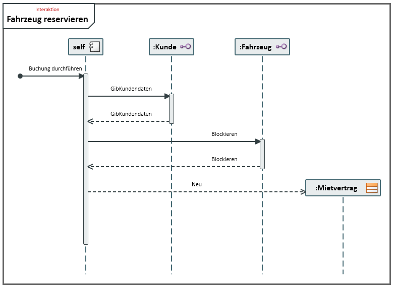
Example of a Sequence Diagram
Further Information
