A state diagram is a behavior diagram of Unified Modeling Language (UML). It displays all states as well as the connected transitions of the depicted state machine.
You can use the established MID modeling tool to create State Diagrams.
Test the Innovator Enterprise Modeling Suite for free.
Definition
The state diagram is a behavior diagram and graphically depicts a state machine. It specifies either a system's behavior or the permissible use of a system's interfaces.
A state diagram gives an overview of states which the state machine being displayed can assume at runtime, e.g. a single object or a (sub)system; it then depicts which state changes and transitions occur based on which event. In doing so, a state diagram describes a finite machine which is in a set of finite states at each point in time.
 The icon is of a diagram with a state in it.
Owner Hierarchy/Prerequisites
- A state diagram shows the contents of precisely one state machine
- The state diagram always shows the complete state machine
- Each state machine needs one behaviored classifier; its states should be described by the machine
Use
The state diagram can be created in the model structure below a behavior-specific classifier.
Dependencies between states and elements from other diagrams are shown in the whiteboard diagram.
Elements in the State Diagram
The following model elements can be shown as nodes and edges in state diagrams:
| Icon | Element | Description |
|---|---|---|

|
State Machine |
A state machine describes a system using states and transitions between these states. A state machine describes a hypothetical machine ("finite machine") which always exists within a set of finite states. State machines primarily map behaviors of classes. Unlike activities which describe activities, states which an object can have during its lifecycle are set in state machines. Conditions and controls are used to set which transitions (state transitions) can be executed. |

|
Region | Regions are used to model parallel flows. Each state machine contains at least one region. Each region contains multiple states; one of these states is always active. |

|
Init State | An init state shows the starting point for entering a state machine. This is the starting point which flows to the first state in the machine. |

|
Final State |
The final state shows the end point of a state machine. The state machine has finished running once this point is reached. The final state takes in the classifier and does not leave it. |

|
Terminator |
Reaching a terminator cancels the state machine's execution and also ends the lifecycle of the classifier being described at the same time. |

|
State |
A simple state maps a situation for which a special condition applies during its progression. A state is used to model a situation; it executes a relatively long-lasting task. The system is in the respective state while the task is being processed. The following rules apply for states:
|

|
Entry point | Entry points merge similar incoming transitions into one composite state. |

|
Exit point |
Exit points combine similar outgoing transitions into one composite state. |

|
Shallow history |
A shallow history stores the last active substate of a composite state once it is left. |

|
Deep history |
A deep history stores the last active substate of all hierarchy levels of a composite state once it is left. |

|
Trigger |
Triggers are used to trigger internal or external transitions. |

|
Decision |
Decisions enable single or multiple transitions to be selected using a decision criteria. |

|
Fork/join |
Forking splits a transition into multiple parallel target states. Joining ends this. |

|
Junction |
Junctions can be used for transitions nested one after another. |
|
|
Transition |
A transition is a directed relationship between one source and one target state. Transitions can be used for moving from one state to another. The source state is inactive for this and the target state is active. You can enter a condition for a transition if required. The transition will then only be run through if the condition is met at the time of the evaluation. |
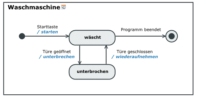
Example of a State Diagram
This chapter contains the topics:
Further Information
