A process map provides a clear depiction of the dependencies of business processes, organizational units and IT elements.
You can use the established MID modeling tool to create a Process Map.
Test the Innovator Enterprise Modeling Suite for free.
Definition
The process map is used for giving an overview of business processes and for this reason does not have a certain notation that must be used. There are many ways to model the process outlined.
 The icon is of a diagram with process arrows.
Use
A process map presents processes, organizational units and IT elements and their relationships.
The process map can be added to a whiteboard diagram as a node.
Dependencies between processes and elements from other diagrams are shown in the whiteboard diagram.
Elements in the Process Map
Node
The following model elements can be shown as nodes in the process map.
| Icon | BPMN Element | Brief Description |
|---|---|---|

|
Process |
A process is sequence or flow of activities in an organization; the aim of a process is to complete a certain task. There is a range of options for modeling a process. You can link the process node to a BPMN process by drag-and-drop, for example, to express that it is realized by this BPMN process. |

|
Management Process | Special node representation for directive processes. |

|
Support Process | Special node representation for subsidiary processes. |

|
Organizational Unit |
An organizational unit is human resources responsible for tasks in an organizational structure, e.g. a department. |

|
IT Element | An IT element is a resource used in the company to execute a process. |

|
Information Object | You can link an information object with a business object or structure definition at a later stage. It can be linked with processes or organizational units using information flows. |


|
Decision Junction Point |
In contrast to the other concept nodes, a decision or junction point (stereotype «junction») acts as a branching or merging point for connections. Since, for the modeling, the name is of secondary importance, an optional property is displayed instead of the name: the condition for branching or merging. The condition can have any content, it can be empty or can have the same content multiple times. |
Edges
Edges portray sequences, flows, relationships or assignments in the process map.
You can use the display options to hide the name in the diagram and display a stereotype property instead, which, for example, can express a transition condition in process sequences.
| Icon | BPMN Element | Brief Description |
|---|---|---|

|
Process Sequence |
A process sequence is a directional relationship between processes and can be split or merged at junction points. Since, for the modeling, the name of the process sequence is of secondary importance, an optional property is displayed instead of the name: the condition for the order of the connected processes. The condition can have any content, it can be empty or can have the same content multiple times. |

|
Resource Connection | A resource connection creates a connection between two resources. |

|
Resource Assignment | A resource assignment creates a new relationship between a process and an IT element or organizational unit. |

|
Information flow | An information flow models information going in the direction shown. Apart from the junction point, all elements can be connected by information flows. You can optionally also integrate the information object itself into the flow, if you want to model the information to be reusable rather than modeling a simple connection. |

|
Concept Connection | A concept connection edge adds elements which are already connected via a relationship from the concept connection edge to the diagram. |
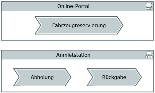
Example of a Process Map