A Data Vault diagram is a stereotype of the entity relationship diagram. It is used for modeling object information in a Data Warehouse along with the corresponding relationships.
You can use the established MID modeling tool to create Data Vault Diagrams.
Test the Innovator Enterprise Modeling Suite for free.
Definition
A Data Vault diagram is a diagram that is based on the entity relationship notation for the graphical display (modeling) of object information in a Data Warehouse and the relationships of this object information. Use it to create a normalized model of your data object without redundancies.
 The icon is of a diagram with an architecture in it.
Use
Data Vault is a modeling technology for Data Warehouses that offers a high level of flexibility for enhancements and the full historization of data. It enables the significant parallelization of data load processes. Data Vault modeling development by Daniel Linstedt began in 1990 and was published for the first time in 2000. It is a combination of relational database modeling with third normal form (3NF) and the star schema.
During modeling, all information that belongs to an object is placed into one of three categories and is strictly separated from the other categories.
-
Hub
Information that uniquely describes an object, i.e. its identity
-
Link
Relationships between the objects
-
Satellite
Attributes that describe an object (hub) or an object relationship (link)
Methodically, the Data Vault standard has many advantages, from high flexibility for enhancements and the full historization of data to the significant parallelization of the data load processes for your data warehouse. Thanks to standardization, the process can be quickly transferred to different projects and can be automated with excellent results.
Data Vault diagram notations are configured in the display options and available in the diagram.
Innovator offers the following diagram notations for Data Vault diagrams:
-
Chen
Notation in accordance with Peter Pin-Shan Chen with (min,max) cardinalities
-
DSA
Notation in accordance to data structure analysis
-
James Martin
Notation in accordance with James Martin, Bachmann and Odell (also know as "crow's foot" notation)
-
SERM
Notation in accordance with structured entity relationship modeling from Prof. Dr. Elmar J. Sinz
-
UML
Notation in accordance with Unified Modeling Language
-
IDEF1X
Notation in accordance with IDEF1X standard (U.S. authority standards FIPS 184)
The main difference between these notations is how they display relationships, whose cardinalities are illustrated with various different graphic icons or formal texts in different places. SERM notation arranges entities in a sort of hierarchy from left to right.
Attention
SERM notation changes how nodes are arranged in the diagram if they were not previously set out in a SERM-compliant way.
Opening the diagram as read-only temporarily changes the layout to comply with SERM but does not save it.
Data Vault Diagram Elements
Nodes
The following model elements can be shown as nodes in Data Vault diagrams.
| Icon | Element | Description |
|---|---|---|

|
Hub Entity |
A hub entity describes a core object of the business logic (e.g. a product) that is normally extremely stable, which contributes to the durability of the data model. A hub is used to save a business key that can also be composed of multiple keys. A hub does not contain any foreign keys. A business key is an object that is used by users of a system, by business processes and by programs to find and identify business objects and to find relationships between business objects. |

|
Link Entity |
A link entity depicts the relationships between the business objects, e.g. between the customer and the product. A link depicts the existence of a business relationship. This business relationship must always be unique, specific and comprehensible on the basis of business rules. A link is always depicted as a separate entity and contains neither business keys nor descriptive data, since hubs or satellites are used for this. |

|
Satellite Entity |
The satellite entity stores all information that describes the hub entity or link entity. A satellite is an object that does not contain either a primary key or a business key. All information describing the business object (hub) or a business relationship (link) is saved in the satellite. This takes place in accordance with whether the satellite is linked with a hub or a link. |

|
Point-in-Time Table |
Point-in-time (PIT) tables are a kind of wizard that enables faster access to certain hubs or satellites in the data model. PIT tables should be used only if no performance problems are to be expected, since they are not necessary for the basic functions of the data model. PIT tables can contain the business key of a hub. This can make sense to avoid having to access the hub itself again. A point-in-time table is always assigned to a hub and its corresponding satellites and should not be used for multiple hubs and links. |

|
Bridge Table |
Bridge tables are very similar to PIT tables. They also aim to accelerate queries to the system and to accelerate the system itself. The difference from a PIT table is that a bridge table is conceived for the connection of multiple hubs. It is therefore another type of link. Like a PIT table, a bridge table should not contain any information from a satellite. However, a bridge table can contain multiple keys from hubs or links. All session keys of the connected hubs and links must be listed in the bridge table to enable accesses to the hub and link entities. |
Edges
Edges depict relationships between dimension levels in Data Vault diagrams.
| Icon | Element | Description |
|---|---|---|

|
1:1 | Each entity in the first entity set is linked to precisely one entity in the second entity set and vice versa. |

|
1:C |
Each entity in the first entity set cannot be linked to more than one entity in the second entity set. Each entity in the second entity set is linked to precisely one entity in the first entity set. |

|
1:M |
Each entity in the first entity set can be linked to at least one entity in the second entity set. Each entity in the second entity set is linked to precisely one entity in the first entity set. |

|
1:MC |
Each entity in the first entity set can be linked to any number of entities in the second entity set. Each entity in the second entity set is linked to precisely one entity in the first entity set. |

|
C:C | Each entity in the first entity set cannot be linked to more than one entity in the second entity set. and vice versa. |

|
C:M |
Each entity in the first entity set is linked to at least one entity in the second entity set. Each entity in the second entity set can be linked with at least one entity in the first entity set. |

|
C:MC |
Each entity in the first entity set can be linked to any number of entities in the second entity set. Each entity in the second entity set can be linked with at least one entity in the first entity set. |

|
ER Foreign Keys | Creates a foreign key for a suitable relationship within entities or R types. |
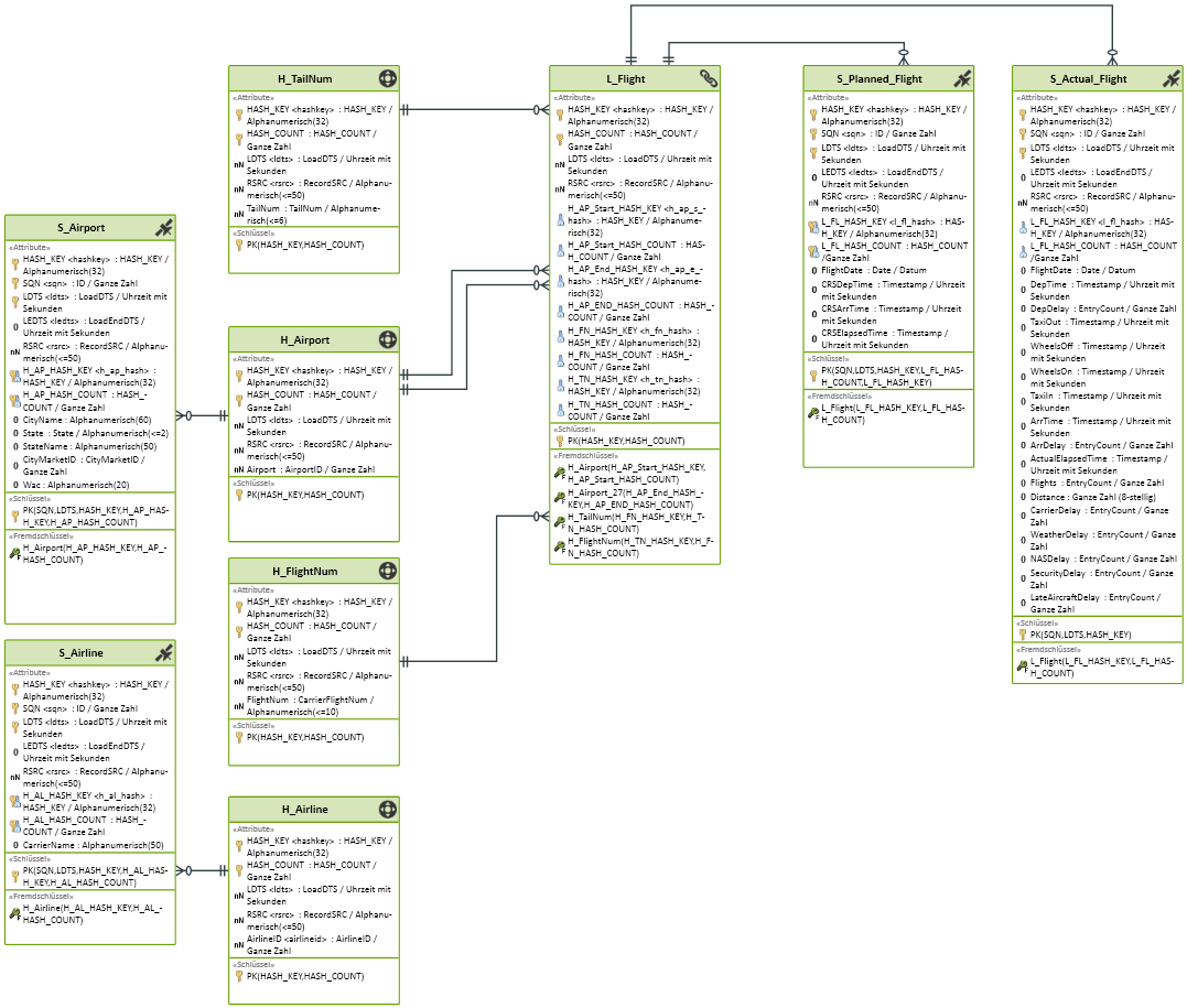
Data Vault Diagram Example