The deployment diagram is a structure diagram of Unified Modeling Language (UML). It shows assignment of artifacts, e.g. from software components, to hardware elements, as well as communication links and dependencies between the hardware elements.
You can use the established MID modeling tool to create Deployment Diagrams.
Test the Innovator Enterprise Modeling Suite for free.
Definition
A deployment diagram shows how components are distributed to computer nodes.
The deployment diagram is a structure diagram. It typically displays computer nodes, components, artifacts, form specifications, connections and deployment relationships.
 The icon is of a diagram with a node in it.
Use
The deployment diagram models how the system's artifacts are deployed to computer nodes upon runtime. Communication links and dependencies between these nodes are also shown.
Elements in the Deployment Diagram
Node
The following model elements can be displayed as nodes in deployment diagrams:
| Icon | Element | Brief Description |
|---|---|---|

|
Nodes | A node splits a resource that artifacts can be split onto. |

|
Device | The special node device shows a particular hardware type. |

|
Execution Environment |
The special node execution environment shows a particular software type. |

|
Artifact | Artifacts show a physical information entity, e.g. models, source code, scripts or documents which are created or required in the development process or runtime of your system. |

|
Deployment specification | The special artifact deployment specification controls how linked artifacts are deployed to nodes. |

|
Instance Description | The instance description uses an example to describe a unit of the modeled system available at runtime |

|
Global Condition | A global condition is a Boolean term that specifies the semantic of one or more model elements. |
Edges
Edges in deployment diagrams show associations, generalizations or dependency relationships.
| Icon | Element | Brief Description |
|---|---|---|

|
Communication path | The communication path is a special type of association that enables the linked nodes to exchange messages. |
|
|
Link | A link is an association's instance that is used for creating a link to another instance description. The association to be instanced is queried upon creation. |

|
Generalization | A generalization is a directed relationship from one special classifier to one general classifier. Instances of the special classifier are also instances of the general classifier in turn. |

|
Usage dependency | Usage dependency is a directed relationship that specifies that an artifact will be split into a node. |

|
Manifestation | A manifestation is a dependency relationship that shows that an artifact physically realizes the linked model element. |

|
Public element import | The public element import is a directed relationship to an imported model element; this can then be transitively imported by other namespaces. |

|
Private element import | The private element import is a directed relationship to an imported model element; this can then not be indirectly imported by other namespaces. |

|
Communication edge | Adds an existing communication edge to a node. |

|
Membership | Adds an existing membership edge to a node. |

|
Directed relationship edge | Adds an existing directed relationships edge to a node. |
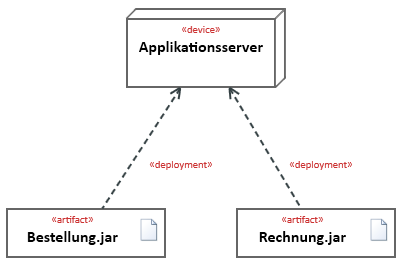
Example for a Deployment Diagram
Further Information
