The component diagram is a structure diagram of Unified Modeling Language (UML). It depicts a certain view of the structure of the modeled system. The display typically comprises components with their interfaces. It also shows how components are linked with each other using dependency relationships.
You can use the established MID modeling tool to create Component Diagrams.
Test the Innovator Enterprise Modeling Suite for free.
Definition
The component diagram is a structure diagram. The display typically comprises components with their interfaces and/or ports. It also shows how components are linked with each other using dependency relationships. A component diagram often contains notation elements for showing the inner workings of a component. These are also primarily shown in classes- or composite structure diagrams, e.g. classes or parts.
The component diagram is primarily used for modeling component-based software systems in software development.
 The component diagram icon shows a diagram with a component icon.
Use
A component diagram supports the modeler when graphically showing the rough structure of the systems and services that are provided or used by sub components via interfaces.
Components and their relationships to each other are modeled for various different purposes.
- Customers can identify what the structure of the completed system will look like at an early stage.
- A structure is set by the system's developers.
- Authors of the documentation and help are given an idea of what to write about.
- Reusability is facilitated by encapsulation of internal details.
Package diagrams offer a greater degree of freedom in structuring the system since packages do not explicitly need to correspond to a system component.
Elements in the Component Diagram
Node
The following model elements can be displayed as nodes in component diagrams:
| Icon | Element | Brief Description |
|---|---|---|

|
Component | Components are modular parts of a system that are structured so that they could be replaced in their environment by another, equivalent component. A component separates its inner structure from the outside as a module and instead provides a set of interfaces or ports that exist or are required. |

|
Interface |
An interface declares a list of attributes, operations and signal receivers with public visibility. If a classifier provides an interface, this ensures that it realizes all of the interface's operations and implements all attributes in a suitable way. A classifier which needs an interface expects a second classifier that realizes the interface to provide operations and attributes suitable for use. |

|
Class |
A class contains the description and structure of objects which can be created using it (templates for objects). A class is defined by its attributes and operations. If you drag the class to an existing class, the newly-created class becomes the inner class of the existing class. |

|
Artifact | Artifacts show a physical information entity, e.g. models, source code, scripts or documents which are created or required in the development process or runtime of your system. |
Edges
Edges in component diagrams represent interfaces or show dependencies between the diagram's nodes.
| Icon | Element | Brief Description |
|---|---|---|

|
Provided Interface | A provided interface is an interface that realizes, and therefore offers, a classifier. |

|
Required Interface | A required interface is an interface that a classifier requires so it can function. |

|
Use | A use is a dependency relationship that shows that the element uses the linked element. |

|
Abstraction | An abstraction is a directed relationship that demonstrates that the element shows an abstraction of the linked element. |

|
Realization | A realization is a directed relationship that demonstrates that the element shows a realization of the linked element. |

|
Public Element Import | The public element import is a directed relationship to an imported element; this can then be transitively imported by other namespaces. |

|
Private Element Import | The private element import is a directed relationship to an imported element; this can then not be indirectly imported by other namespaces. |

|
Component Realization | A component realization is a dependency relationship that shows that the classifier realizes part of the linked components. |

|
Interface Realization | An interface realization is a dependency relationship that sets that the classifier realizes the behavior specified in the linked interface. |

|
Create Default | A create default is a special dependency relationship that indicates that newly-created elements are created in the target container. |

|
Association Edge | Adds an existing association edge to an element. |

|
Socket/Ball Edge | Adds an existing socket/ball edge to an element. |
* These edges are available in the standard profile for package diagrams.
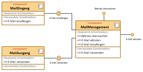
Example for a Component Diagram
Further Information
