A composite structure diagram is a structure diagram of Unified Modeling Language (UML). It graphically displays the internal structure and interaction relationships of classifiers.
You can use the established MID modeling tool to create Composite Structure Diagrams.
Test the Innovator Enterprise Modeling Suite for free.
Definition
The composite structure diagram shows the inner structure and interaction relationships of classifiers. It shows part/whole relationships as composite structures.
 The icon is of a diagram with a composite structure in it.
Use
Decomposition of a whole into parts is mapped as structural/static composite structure. Unlike class diagrams, the parts form a set structure template at runtime which defines a certain context of the parts. Set relationships (associations, links) between instances linked in a composition can be described in more detail than is possible in a class diagram.
The function and parts of the system needed for this function are viewed as structurally dynamic composite structure. The structure of roles which work together and carry out the function are shown in a collaboration. The dynamic of the collaboration of roles is shown in the sequence diagram.
Composite Structure Diagram Elements
Node
The following model elements can be displayed as nodes in the composite structure diagram:
| Icon | Element | Brief Description |
|---|---|---|

|
Class | A UML class defines a classification for a set of objects with common semantics, properties and behaviors. |

|
Component | Components are modular parts of a system that are structured so that they could be replaced in their environment by another, equivalent component. A component separates its inner structure from the outside as a module and instead provides a set of interfaces or ports that exist or are required. |

|
Node | A node splits a resource that artifacts can be split onto. |

|
Device | The special node device shows a particular hardware type. |

|
Execution Environment |
The special node execution environment shows a particular software type. |

|
Interface |
A UML interface renames a set of properties and operations with a public visibility |

|
Data Type |
A data type combines concrete value ranges and operations defined by these value ranges into one entity. |

|
Signal | A signal is a special classifier that describes data that is exchanged between communication partners |

|
Actor | The actor describes a user of the system and is also the system's trigger at the same time. The actor does not necessarily have to be a person, it can also describe a trigger function. |

|
Use Case | A use case describes how a system is used by its users. The system's actions and communication between actors comprises a result that can be viewed in the form of behaviors which are relevant for one or more actors and/or participants in the system. |

|
Artifact | Artifacts show a physical information entity, e.g. models, source code, scripts or documents which are created or required in the development process or runtime of your system. |

|
Deployment specification | The special artifact deployment specification controls how linked artifacts are deployed to nodes. |

|
Collaboration | Defines a pattern for collaborating with various model elements that have a certain task in common. |

|
Collaboration application | A collaboration application is the application of a pattern defined by a collaboration on certain model elements. |

|
Part | A part defines a component of the structured classifier. |

|
Port | A port defines an interaction point of a classifier with its environment or internal parts. |
Edges
Edges in composite structure diagrams represent communication links or interfaces or show dependencies between the diagram's nodes.
| Icon | Element | Brief Description |
|---|---|---|

|
Connector | A connector defines a communication link to another part or port. |

|
Provided Interface | This interface (ball) is provided by a classifier. The interface provided is queried upon creation of the element. |

|
Required Interface | This interface (socket) is required by a classifier. The interface required is queried upon creation of the element. |

|
Generalization | A generalization is a directed relationship from one special classifier to one general classifier. Instances of the special classifier are also instances of the general classifier in turn. |

|
Interface Realization | An interface realization is a dependency relationship that sets that the classifier realizes the behavior specified in the linked interface. |

|
Component realization | A component realization is a dependency relationship that shows that the classifier realizes part of the linked components. |

|
Dependency | A dependency is a directed relationship that states that the source element depends on the target element. |

|
Abstraction | An abstraction is a directed relationship that demonstrates that the element shows an abstraction of the linked element. |

|
Use | A use is a dependency relationship that shows that the element uses the linked element. |

|
Connector edge | Adds an existing connector edge to an element. |

|
Membership | Adds an existing membership edge to an element. |

|
Directed relationship edge | Adds an existing directed relationships edge to an element. |

|
Socket/Ball Edge | Adds an existing socket/ball edge to an element. |
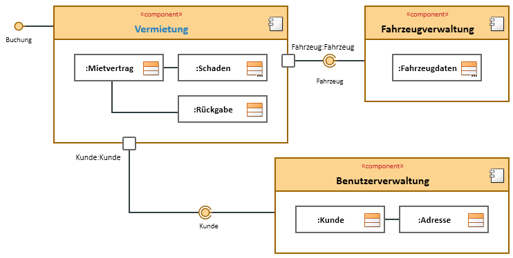
Example for a Composite Structure Diagram
Further Information
