A class diagram is a structure diagram of the Unified Modeling Language (UML) for graphically displaying (modeling) classes, interfaces and their relationships. An object diagram depicts instances of classes at execution time.
You can use the established MID modeling tool to create a Class Diagrams and Object Diagrams.
Test the Innovator Enterprise Modeling Suite for free.
Definition
A class diagram is a structure diagram for displaying classes, interfaces and their relationships. In object orientation, a class is an umbrella term used for describing the whole structure and common behavior of objects (classification). Classes can be used for modeling a defined system in object-oriented analysis and design.
The object diagram is a structure diagram that represents instances of classes at the time of execution as a snapshot of the system.
 The class diagram icon shows a diagram with a class icon.
 The object diagram icon shows a diagram with an object structure icon.
Use
Class diagrams are the central diagram type of UML. They describe a system's classes, its properties, operations and relationships between classes. Class diagrams are implemented in all phases of the software development process.
Modeled contents and vocabulary used needs to be tailored towards the group of persons participating. A class diagram models a partial section of the real world. Only classes and properties which are needed for describing the problem area are taken into consideration.
Differentiations are generally made between the analysis model and the design model when modeling class diagrams:
-
Analysis Model
From an analysis point of view, class diagrams show what the system should achieve from the view of the user. They map classes, attributes, operations and their relationships which should all be contained in the software system developed later from the business perspective of things.
-
Design Model
The analysis model is mapped to the implementation technology in the design model. From a design point of view, class diagrams show how the system needs to be constructed technically so that it can carry out the properties required during analysis. Structures recognized and documented within system analysis are extended to include information required to implement the business model.
Class Diagram Elements
Node
The following model elements can be shown as nodes in class diagrams:
| Icon | Element | Description |
|---|---|---|

|
Class |
A class contains the description and structure of objects which can be created using it (templates for objects). A class is defined by its attributes and operations. If you drag the class to an existing class, the newly-created class becomes the inner class of the existing class. |

|
Interface |
An interface realizes feature use between user and provider. If you drag the interface to a class, the newly-created interface becomes the inner class of the existing class. |

|
Data Type |
A data type combines concrete value ranges and operations defined by these value ranges into one entity. If you drag the data type to a class, the newly-created data type becomes the inner class of the existing class. |

|
Enumeration Type | An enumeration type is a data type with a finite value range. |

|
Primitive Type | A primitive type refers to algebra and operations that are not defined in the model, e.g.. using programming languages or math. |

|
Component | A component defines a modular section of the system which encapsulates its contents and offers a defined function. |

|
Package | A package groups a set of model elements into a group and provides a namespace for this group. Packages can contain other packages as sub packages. |

|
Condition * | A global condition is a Boolean term that specifies the semantic of one or more model elements. |

|
Collaboration | Defines a pattern for collaborating with various model elements that have a certain task in common. |

|
Node | A node splits a resource that artifacts can be split onto. |

|
Execution Environment |
The special node execution environment shows a particular software type. |

|
Device | The special node device shows a particular hardware type. |

|
Artifact | Artifacts show a physical information entity, e.g. models, source code, scripts or documents which are created or required in the development process or runtime of your system. |

|
Signal | A signal is a special classifier that describes data that is exchanged between communication partners |

|
Instance Description * | The instance description uses an example to describe a unit of the modeled system available at runtime |
* These nodes are available in the standard profile for object diagrams.
Features
A class diagram can contain the following features for classes and components:
| Icon | Element | Description |
|---|---|---|

|
Attribute | An attribute is an element that appears identically in a class' object. Its type is used for limiting an attribute's value range. |

|
Operation | Operations realize the behavior of classes and define which types the values which are exchanged are from (parameter). |

|
Literal (enumeration value) | Enumeration values use declaration of the type with names to define all values of the enumeration type. The order is also set here. |

|
Template Parameter | Formal template parameters are used as wildcards for actual template parameters assigned during template connection. |

|
Port | A port defines an interaction point of a classifier with its environment or internal parts. |

|
Slot | A slot enters a concrete value for a property of an instance description. |

|
Reception | A reception is a behavior property that shows that a certain signal can be received and processed. |

|
Parameter | A parameter is a behavior property's argument. |
Edges
Edges in class diagrams show associations, generalizations or dependencies.
| Icon | Element | Description |
|---|---|---|

|
1:0..1 | Set that an instance of this classifier can be linked to no more than one instance of the second classifier. Vice versa, each instance of the second classifier can be linked with precisely one instance of this classifier. |

|
1:1 * | Set that an instance of this classifier can be linked with precisely two instances of the second classifier; vice versa, an instance of the second classifier can be related to one instance of this classifier. |

|
1:M | Set that each instance of the classifier can be linked to any number of instances of the second classifier. |

|
1:M directed | Set that each instance of this classifier can be linked to any number of instances of the second classifier. Vice versa, set that each instance of the second classifier can be linked to precisely one (hidden!) instance of this classifier. |

|
M:N | Set that each instance of this classifier can be linked to any number of instance of the second classifier, and vice versa. |

|
M:N directed | Set that each instance of this classifier can be linked to any number of instances of the second classifier. Vice versa, set that each instance of the second classifier can be linked to any number of (hidden!) instances of this classifier. |

|
Association class | An association class is a class with attributes and operations that describe associations between other classes. |

|
Aggregation | Set that an instance of this classifier can contain (whole) instances of the second classifier (part). However, the instances of the second classifier can also exist without need of the first or be part of other aggregations. |

|
Composition |
Set that an instance of this classifier can contain (whole) instances of the second classifier (part) and is responsible for its existence. Destruction of the first classifier causes the second classifier's instances included to be destroyed too. Each instance of the second classifier can only be part of one instance of the first classifier at one given time. |

|
Generalization | Generalizations, associations, dependencies, uses, abstractions, realizations etc. express various types of relationships between classes and describe the structure classes. |

|
Interface Realization | An interface realization is a dependency relationship that sets that the classifier realizes the behavior specified in the linked interface. |

|
Use | A use is a dependency relationship that shows that the element uses the linked element. |

|
Realization | A realization is a directed relationship that demonstrates that the element shows a realization of the linked element. |

|
Abstraction * | An abstraction is a directed relationship that demonstrates that the element shows an abstraction of the linked element. |

|
Dependency | A dependency is a directed relationship that states that the source element depends on the target element. |

|
Component realization | A component realization is a dependency relationship that shows that the classifier realizes part of the linked components. |

|
Public element import or package import | The public element import or package import is a directed relationship to an imported element or package; this can then be transitively imported by other namespaces. |

|
Private element import or package import | The private element import or package import is a directed relationship to an imported element or package; this can then not be indirectly imported by other namespaces. |

|
Association edge * | Adds an existing association edge to an element. |

|
Membership | Adds an existing membership edge to an element. |

|
Directed relationship edge | Adds an existing directed relationships edge to an element. |

|
Socket/Ball Edge | Adds an existing socket/ball edge to an element. |
* These edges are available in the standard profile for object diagrams.
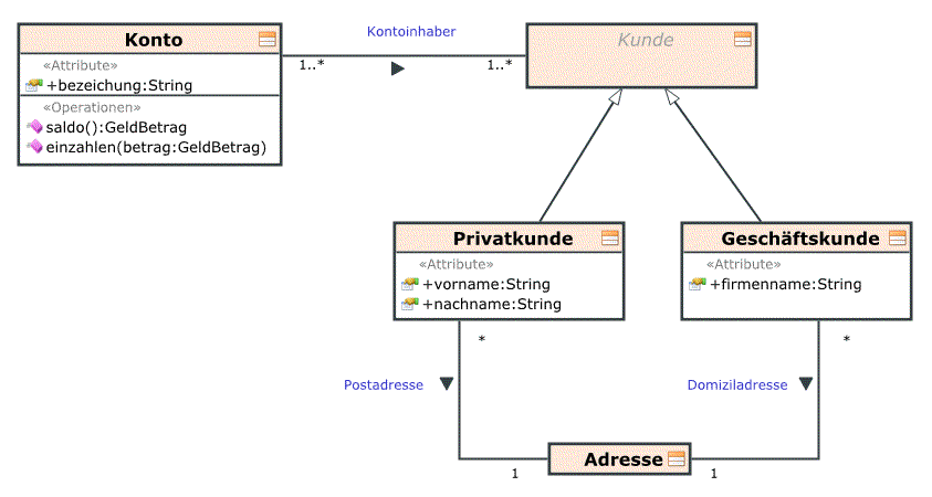
Example of a Class Diagram
Further Information
