ArchiMate® diagrams are used for representing and developing business architectures. They depict the relationships between the business areas, their processes, applications, information structures, and infrastructures etc.
You can use the established MID modeling tool to create a ArchiMate® Diagram.
Test the Innovator Enterprise Modeling Suite for free.
Definition
ArchiMate® diagrams are used for representing and developing business architectures.
The relationships between the business areas, their processes, applications, information structures and infrastructures etc. are modeled.
 The icon is of a diagram with an architecture in it.
Owner Hierarchy/Prerequisites
ArchiMate® diagrams represent elements of business areas and their relations using different viewpoints.
ArchiMate® diagrams and viewpoints are provided as concept diagrams. Use dynamic concept diagrams for focusing on connections between certain concepts and their neighboring concepts.
The following diagrams and viewpoints are differentiated between in Innovator:
ArchiMate® Diagrams
- ArchiMate Diagram
- Strategy Layer Diagram
- Business Layer Diagram
- Application Layer Diagram
- Technology Layer Diagram
- Physical Layer Diagram
- Implementation and Migration Diagram
Motivation
- Stakeholder Viewpoint
- Goal Realization Viewpoint
- Requirements Realization Viewpoint
- Motivation Viewpoint
Strategy
- Strategy Viewpoint
- Capability Map Viewpoint
- Value Stream Viewpoint
- Outcome Realization Viewpoint
- Resource Map Viewpoint
Composition
- Organization Viewpoint
- Application Structure Viewpoint
- Information Structure Viewpoint
- Technology Viewpoint
- Layered Viewpoint
- Physical Viewpoint
Support
- Product Viewpoint
- Application Usage Viewpoint
- Technology Usage Viewpoint
Cooperation
- Business Process Cooperation Viewpoint
- Application Cooperation Viewpoint
Realization
- Service Realization Viewpoint
- Implementation and Deployment Viewpoint
Implementation and Migration
- Project Viewpoint
- Migration Viewpoint
- Implementation and Migration Viewpoint
ArchiMate® Risk and Security Overlay
- Risk and Security Viewpoint
Use
ArchiMate® diagrams and viewpoints can be added as nodes in a whiteboard diagram.
The dependencies between elements from different diagrams are displayed in a whiteboard diagram.
ArchiMate® Diagrams and their Elements
Viewpoints
The following viewpoints and others can be created as ArchiMate® diagrams.
| Icon | Element | Brief Description |
|---|---|---|

|
Application Usage Viewpoint |
Shows use of applications e.g. in business processes. |

|
Business Process Cooperation Viewpoint |
Shows relationships between various business processes. |

|
Layered Viewpoint |
Provides an overview of architecture(s). |

|
Goal Realization Viewpoint |
Focuses on refining the initial, superordinate targets in concrete (partial) targets using the aggregation relationship and then in requirements and constraints using the realization relationship. |

|
Implementation and Migration Viewpoint |
Used to model the relationships between the programs and projects and the parts of the architecture that they implement. |

|
Information Structure Viewpoint |
Shows the structure of information used within the company. |

|
Technology Usage Viewpoint |
Shows how technology is used by applications. |

|
Migration Viewpoint |
Used to model the transition from an existing architecture to a target architecture. |

|
Motivation Viewpoint |
Covers the entire motivational aspect and allows use of all motivational elements. |

|
Project Viewpoint |
Primarily used to model management of architecture changes. |

|
Requirements Realization Viewpoint |
Focuses on modeling the realization of requirements and constraints by means of core elements, such as actors, services, processes, application components, etc. |

|
Stakeholder Viewpoint |
Focuses on modeling of stakeholders, drivers, evaluations of these drivers and initial targets to address these drivers and evaluations. |

|
Strategy Viewpoint |
Provides a high-level strategic overview of the strategies of the enterprise, its capabilities, value streams, and resources, and the envisaged outcomes. |

|
Value Stream Viewpoint |
Shows an overview of value-creating steps in the enterprise and the capabilities that support these. |
Nodes
The following model elements and others can be displayed as nodes in ArchiMate® diagrams.
| Icon | Element | Brief Description |
|---|---|---|

|
Business Event |
Represents an organizational state change. |

|
Business Function |
Represents a collection of business behavior based on a chosen set of criteria (typically required business resources and/or competencies), closely aligned to an organization, but not necessarily explicitly governed by the organization. |

|
Business Interaction |
Represents a unit of collective business behavior performed by (a collaboration of) two or more business actors, business roles,or business collaborations. |

|
Business Collaboration |
Represents an aggregate of two or more business internal active structure elements that work together to perform collective behavior. |

|
Business Object |
Represents a concept used within a particular business domain. |

|
Business Process |
Represents a sequence of business behaviors which achieve a specific result, such as a defined set of products or business services. |

|
Business Role |
Represents the responsibility for performing specific behavior, to which an actor can be assigned, or the part an actor plays in a particular action or event. |

|
Business Service |
Represents explicitly defined behavior that a business role, business actor, or business collaboration exposes to its environment. |

|
Business Interface |
Represents a point of access where a business service is made available to the environment. |

|
Product |
Represents a coherent collection of services and/or passive structure elements, accompanied by a contract/set of agreements, which is offered as a whole to (internal or external) customers. |

|
Representation |
Represents a perceptible form of the information carried by a business object. |

|
Location |
Represents a conceptual or physical place or position where concepts are located (e.g. structure elements) or performed (e.g. behavior elements). |

|
Contract |
Represents a formal or informal specification of an agreement between a provider and a consumer that specifies the rights and obligations associated with a product and establishes functional and non-functional parameters for interaction. |

|
Business Actor |
Represents a business entity that is capable of performing behavior. |

|
Data Object |
Represents data structured for automated processing. |

|
Application Function |
Represents automated behavior that can be performed by an application component. |

|
Application Interaction |
Represents a unit of collective application behavior performed by (a collaboration of) two or more application components. |

|
Application Collaboration |
Represents an aggregate of two or more application internal active structure elements that work together to perform collective application behavior. |

|
Application Component |
Represents an encapsulation of application functionality aligned to implementation structure, which is modular and replaceable. |

|
Application Interface |
Represents a point of access where application services are made available to a user, another application component, or a node. |

|
Application Service |
Represents an explicitly defined exposed application behavior. |

|
Artifact |
Represents a piece of data that is used or produced in a software development process, or by deployment and operation of an IT system. |

|
Device |
Represents a physical IT resource upon which system software and artifacts may be stored or deployed for execution. |

|
Node |
Represents a computational or physical resource that hosts, manipulates, or interacts with other computational or physical resources. |

|
Communication Network |
Represents a set of structures that connects nodes for transmission, routing, and reception of data. |

|
Path |
Represents a link between two or more nodes, through which these nodes can exchange data, energy or material. |

|
System Software |
Represents software that provides or contributes to an environment for storing, executing, and using software or data deployed within it. |

|
Technology Function |
Represents a collection of technology behavior that can be performed by a node. |

|
Technology Interface |
Represents a point of access where technology services offered by a node can be accessed. |

|
Technology Service |
Represents an explicitly defined exposed technology behavior. |

|
Requirement |
Represents a statement of need defining a property that applies to a specific system as described by the architecture. |

|
Meaning |
Represents the knowledge or expertise present in, or the interpretation given to, a concept in a particular context. |

|
Assessment |
Represents the result of an analysis of the state of affairs of the enterprise with respect to some driver. |

|
Constraint |
Represents a factor that limits the realization of goals. |

|
Principle |
Represents a statement of intent defining a general property that applies to any system in a certain context in the architecture. |

|
Stakeholder |
Represents the role of an individual, team, or organization (or classes thereof) that represents their interests in the effects of the architecture. |

|
Driver |
Represents an external or internal condition that motivates an organization to define its goals and implement the changes necessary to achieve them. |

|
Value |
Represents the relative worth, utility, or importance of a concept. |

|
Goal |
Represents a high-level statement of intent, direction, or desired end state for an organization and its stakeholders. |

|
Deliverable |
Represents a precisely-defined result of a work package. |

|
Gap |
Represents a statement of difference between two plateaus. |

|
Plateau |
Represents a relatively stable state of the architecture that exists during a limited period of time. |

|
Work Package |
Represents a series of actions identified and designed to achieve specific results within specified time and resource constraints. |

|
Grouping |
Aggregates or composes concepts that belong together based on some common characteristic. |

|
Junction |
Used to connect relationships of the same type. |
The ArchiMate® diagram contains not only those elements which can be seen but also those which can be shown linked to the visible elements. These dependent elements can often be made visible using the respective configuration.
Edges
In ArchiMate® viewpoints, edges represent relationships.
| Icon | Element | Brief Description |
|---|---|---|

|
Specialization |
Represents that an element is a particular kind of another element. |

|
Composition |
Represents that an element consists of one or more other concepts. |

|
Aggregation |
Represents that an element combines one or more other concepts. |

|
Assignment |
Represents the allocation of responsibility, performance of behavior, storage or execution. |

|
Realization |
Represents that an entity plays a critical role in the creation, achievement, sustenance or operation of a more abstract entity. |

|
Triggering |
Represents a temporal or causal relationship between elements. |

|
Flow |
Represents transfer (e.g. of information, goods or money) from one element to another. |

|
Influence |
Represents that an element affects the implementation or achievement of some motivation element. |

|
Association |
Represents an unspecified relationship or one that is not represented by another ArchiMate relationship. |

|
Directed Association |
Represents a directed, unspecified relationship or one that is not represented by another ArchiMate relationship. |

|
Serving |
Represents that an element provides its functionality to another element. |

|
Access |
Represents the ability of behavior and active structure elements to observe or act upon passive structure elements. |

|
Read Access |
Represents the ability of behavior and active structure elements to read passive structure elements. |

|
Read/Write Access |
Represents the ability of behavior and active structure elements to read and write passive structure elements. |

|
Write Access |
Represents the ability of behavior and active structure elements to write passive structure elements. |
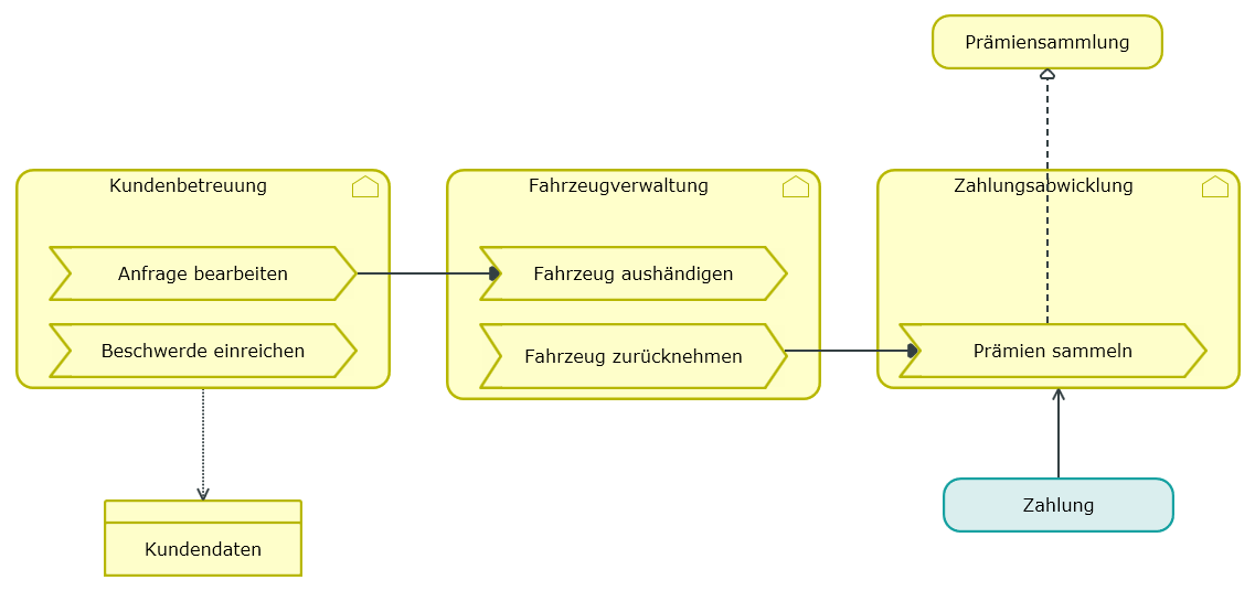
Example for an ArchiMate® Diagram
Further Information
