Getting Started with Innovator for Enterprise Architects
Innovator for Enterprise Architects is the integrated tool for enterprise architects, for analyzing and designing business areas using the modeling language ArchiMate®.
What do you want to do?
| Task | Help Topic |
|---|---|
| Define a high level view of business processes |
 Describing Business Processes Describing Business Processes |
| Map how applications support business processes |
Creating Applications and Dependencies to Business Processes |
| Map how the application level uses the infrastructure |
Modeling Hardware and Software Components Used by Applications |
| Show interrelations between modeling levels |
Displaying the Entire Architecture |
| Describe and comment on model elements |
Creating Specification Texts and Comments |
Describing Business Processes
Defining a High Level View of Business Processes
Note
In ArchiMate®, colors represent different pieces of information. The default color scheme categorizes the elements into the respective level of the enterprise architecture.
To use this color scheme, which is defined in the model template, select View>Colors>Method Colors.
How to proceed
-
Activate the Start tab in the ribbon.
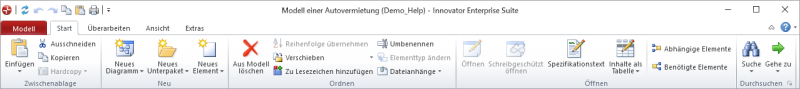
This tab contains the New group.
-
Activate the
 New Diagram button from the New group.
The gallery with templates for new diagrams appears.
-
Select the
 Business Process Cooperation Viewpoint template from the gallery.
An empty Business Process Cooperation Viewpoint is created and opened in the document area. You can now use this diagram to create business processes, services, actors and other elements at the business level.
Tip
You can create various types of diagrams in Innovator models in this way. The types of diagram templates available in the gallery primarily depend on the model template used and the user role selected in a model.

Work in the Business Process Cooperation Viewpoint you just created for the following steps.
How to proceed
-
Activate the Design tab in the ribbon if this is not the active tab.
This tab contains the Create Diagram Content group.
-
In the gallery for the Create Diagram Content group, click on the
 Role icon.
 -
Move the mouse over the diagram.
The icon for the role is now "attached" to your mouse pointer and follows the movement of the mouse.
-
Click again with the left mouse button where you want to place the role.
The role is created and is initially given a default name. You can immediately change this.
Alternative procedure:
-
As above
-
In the gallery for the Create Diagram Content group, click on the
Role icon and hold down the left mouse button. -
Move the mouse with the left mouse button pressed in the diagram.
The icon for the role is again "attached" to your mouse pointer and follows the movement of the mouse.
-
Release the left mouse button where you want to position the role
The role is created and is initially given a default name. You can immediately change this.
Tip
You can create various types of diagram elements in Innovator diagrams in this way. The types of elements available in the diagram editor's gallery primarily depend on the diagram type used, the model template used and the user role selected in a model.
Context
You can create a business process in the same way as a role (see above).
Alternatively, you can also create a business process by connecting it directly to an existing role. This expresses the fact that this role is responsible for this business process.
How to proceed
-
Select the role in the diagram
The selected role is shown with a blue selection frame. There are various semitransparent icons on the right-hand side that are highlighted if you hover the mouse over them – this is called the carousel.
-
From the carousel, select the
 Link icon and keep the left mouse button pressed.
 -
With the left mouse button pressed, drag the icon to a free point in the diagram.
The position of the link that will be created is shown when you drag the icon by a blue rubber band line.
-
Release the left mouse button on a free point in the diagram.
A drop-down list with the partner elements permissible for this type of relationship appears. The
 business process will be available in the list, alongside other options.
 -
Left mouse click on this entry.
The business process and the link to the role are created; the business process is initially given a default name. You can immediately change this.
Tip
You can create various kinds of different connection types in Innovator diagrams in this way. The types of elements available in a diagram element's carousel and in the drop-down list primarily depend on the diagram type used, the model template used and the user role selected in a model.
Prerequisites
This example assumes that both business processes to be linked are already in the diagram. Alternatively, you can create a new business process together with the  Triggering relationship, as you did when creating business processes (see above).
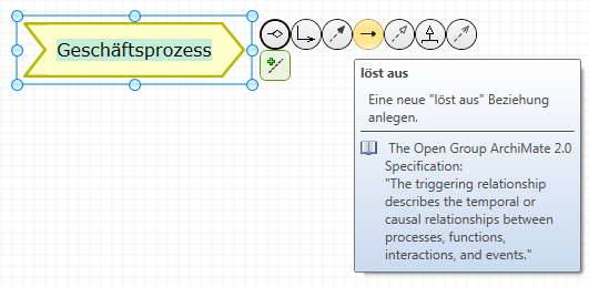
Context
You can connect two business processes together with a Triggering relationship, among other options. This expresses a temporal or causal flow between the business processes.
How to proceed
-
Select a business process in the diagram.
The selected business process is outlined with a blue frame. There are various semitransparent icons on the right-hand side that are highlighted if you hover the mouse over them – this is called the carousel.

-
Select the
Triggering icon from the carousel and keep the left mouse button pressed. -
With the left mouse button pressed, drag the icon onto the business process to be connected.
When dragging, the position of the relationship that will be created is indicated by a blue rubber band line.
-
Let go of the mouse button over the business process which you want to create the connection to.
Tip
You can create various kinds of different types of connections in Innovator diagrams in this way. The types of elements available in a diagram element's carousel and in the drop-down list primarily depend on the diagram type used, the model template used and the user role selected in a model.
Creating Applications and Dependencies to Business Processes
Map how applications support business processes
How to proceed
-
Activate the Start tab in the ribbon.
This tab contains the New group.
-
Activate the
New Diagram button from the New group.The gallery with templates for new diagrams appears.
-
Select the
 Application Usage View template from the gallery.
An empty Application Usage View is created and opened in the document area. You can now use this diagram to describe how components and services are used at the application level of business processes or other components.
Tip
You can create various types of diagrams in Innovator models in this way. The types of diagram templates available in the gallery primarily depend on the model template used and the user role selected in a model.
Work in the application usage view you just created for the following steps.
How to proceed
-
Activate the Design tab in the ribbon if this is not the active tab.
This tab contains the Create Diagram Content group.
-
Select the
 Component icon from the gallery.
 -
Move the mouse over the diagram.
The component icon is now "attached" to your mouse pointer and follows the movement of the mouse.
-
Left-click where you want to place the component.
The component is created and is initially given a default name. You can immediately change this.
The alternative procedure for creating a role (see above) is, of course, also possible in this step.
Tip
You can create various types of diagram elements in Innovator diagrams in this way. The types of elements available in the diagram editor's gallery primarily depend on the diagram type used, the model template used and the user role selected in a model.
Context
You can create a service at the application level in the same way as a component (see above).
Alternatively, you can also create a service at the application level by connecting it directly to an existing component. This expresses that this component realizes the service at the application level and can be used by this.
How to proceed
-
Select the component in the diagram.
The selected component is outlined with a blue frame. There are various semitransparent icons on the right-hand side; if you hover over them with the mouse they are highlighted – this is called the carousel.
-
Select the
 Realization icon from the carousel and keep the left mouse button pressed.
 -
With the left mouse button pressed, drag the icon onto the business process to be connected.
When dragging, the position of the realization that will be created is indicated by a blue rubber band line.
-
Release the mouse button at a free point in the diagram.
A drop-down list with the partner elements permissible for this type of relationship appears. The
 service (application level) will be available in the list, alongside other options.
 -
Left mouse click on this entry.
The service at application level and the realization relation to the component are created; the service at application level is initially given a default name. You can immediately change this.
Tip
You can create various kinds of different connection types in Innovator diagrams in this way. The types of elements available in a diagram element's carousel and in the drop-down list primarily depend on the diagram type used, the model template used and the user role selected in a model.
Prerequisites
This example assumes that the business process to be connected is already in the model and a service (application level) is in the diagram.
Context
You can reuse an existing business process in various diagrams and connect it in the diagram to a service at the application level. This expresses that the service at the application level is used by the business process.
How to proceed
-
Select a business process in the model structure.
The selected business process is outlined with a selection frame.
-
Drag the selected business process with the left mouse button pressed to a free point in the diagram.
-
Release the left mouse button on a free point in the diagram.
The selected business process is inserted at this point in the diagram.
-
Select a service (application level) in the diagram.
The selected service (application level) is outlined with a blue frame. There are various semitransparent icons on the right-hand side; if you hover over them with the mouse they are highlighted – this is called the carousel.
-
Select the
 Used by icon from the carousel and keep the left mouse button pressed.
 -
With the left mouse button pressed, drag the icon onto the business process to be connected.
When dragging, the position of the connection that will be created is indicated by a blue rubber band line.
-
Let go of the mouse button over the business process to which you want to create the connection.
The connection expresses that the service is used by the inserted, connected business process.
Tip
You can insert various types of elements that already exist in the model into Innovator diagrams in this way, in order to describe various aspects of these elements. The types of elements that can be inserted into a diagram primarily depend on the diagram type used, the model template used and the user role selected in a model.
Modeling Hardware and Software Components Used by Applications
Map how the application level uses the infrastructure
How to proceed
-
Activate the Start tab in the ribbon.
This tab contains the New group.
-
Activate the
New Diagram button from the New group.The gallery with templates for new diagrams appears.
-
Select the
 Technology Usage View template from the gallery.
An empty technology usage view is created and opened in the document area. You can now use this diagram to describe how hardware and software are used at the infrastructure level and how components are used at the application level of business processes or other components.
Tip
You can create various types of diagrams in Innovator models in this way. The types of diagram templates available in the gallery primarily depend on the model template used and the user role selected in a model.
Work in the technology usage view you just created for the following steps.
How to proceed
-
Activate the Design tab in the ribbon if this is not the active tab.
This tab contains the Create Diagram Content group.
-
Select the
 Node icon from the gallery.
 -
Move the mouse over the diagram.
The node icon is now "attached" to your mouse pointer and follows the movement of the mouse.
-
Click the left mouse button where you want to position the node.
The node is created and is initially given a default name. You can immediately change this.
The alternative procedure for creating a component (see above) is, of course, also possible in this step.
Tip
You can create various types of diagram elements in Innovator diagrams in this way. The types of elements available in the diagram editor's gallery primarily depend on the diagram type used, the model template used and the user role selected in a model.
Context
You can embed system software in a node. This expresses that the system software is operated on the node.
How to proceed
-
Right-click on the node to open the context menu.
-
Select Show as Container.
The node changes in size and is shown as a container port.
-
As previously described, drag a new piece of system software from the gallery to the container.
The system software is initially given a default name. You can immediately change this.
-
Alternatively, you can drag an existing system software into the container from the diagram.
Tip
You can represent compositions of elements in Innovator diagrams in this way. The types of elements that can be embedded or used as container primarily depend on the diagram type used, the model template used and the user role selected in a model.
Displaying the Entire Architecture
Show interrelations between modeling levels
How to proceed
-
Activate the Start tab in the ribbon.
This tab contains the New group.
-
Activate the
New Diagram button from the New group.The gallery with templates for new diagrams appears.
-
Select the
 Layered View template from the gallery.
An empty Layered View is created and opened in the document area. You can now use this diagram to show all levels of an enterprise architecture in a diagram.
Tip
You can create various types of diagrams in Innovator models in this way. The types of diagram templates available in the gallery primarily depend on the model template used and the user role selected in a model.
Work in the layered view you just created for the following steps.
Prerequisites
This example assumes that the corresponding elements and relationships already exist in the model.
Context
You can insert multiple elements from different levels into a diagram. This also adopts their existing relationships into the diagram.
How to proceed
-
Select the element to be inserted from the model structure.
The selected elements are outlined with a selection frame.
-
Drag the selected elements with the left mouse button pressed to a free point in the diagram.
-
Release the left mouse button on a free point in the diagram.
The selected elements and the relationships between them are inserted at this point in the diagram.
Tip
You can insert various types of elements that already exist in the model into Innovator diagrams in this way. The types of elements that can be inserted into a diagram primarily depend on the diagram type used, the model template used and the user role selected in a model.
Prerequisites
This example assumes that a business process exists in the model which is connected to a business process already occurring in the diagram.
Context
You can add business processes for which a relationship already exists in the model to a diagram via the carousel of the business process that already exists in the diagram.
How to proceed
-
Select the business process in the diagram.
The selected business process is outlined with a blue frame. There are various semitransparent icons on the right-hand side; if you hover over them with the mouse they are highlighted – this is called the carousel.
-
Select the
 Concept connection edge icon from the carousel and keep the left mouse button pressed.
 -
With the left mouse button pressed, drag the icon to a free point in the diagram.
When dragging, the position of the relationship that will be created is indicated by a blue rubber band line.
-
Release the left mouse button on a free point in the diagram.
A drop-down list of the elements in the relationship with the type of the respective relationship appears. The
business process will be available in the list, alongside other options. -
Left mouse click on this entry.
The business process and the connection are inserted.
Tip
You can insert various types of elements that are connected to diagram elements into Innovator diagrams in this way. The types of elements available in the drop-down list primarily depend on the diagram type used, the model template used and the user role selected in a model.
Prerequisites
This example assumes that the elements are connected to the corresponding plateaus or can be manually assigned.
Context
You can assign elements from the enterprise architecture to an architecture plateau by selecting the appropriate label.
To make the assignment clear in the diagram, you can used color labels.
To label changes to elements between plateaus, it is possible to customize the properties of the corresponding elements.
How to proceed
-
To represent the assignments to the plateaus in the diagram in color, jump to the color scheme using View>Colors>Color Label.
The existing color labels are displayed.
-
Select the color label Contained in plateau.
The elements in the diagram are shaded according to the color label.
-
To specify the instance of an element in a plateau, select the element.
The properties for the selected element are displayed in the Properties tool window.
-
Open the Labels area by clicking on the arrow.
The labels available for the element are displayed.
-
For the Contained in plateau label, select which plateau the element occurs in.
The color of the element is customized in accordance with the assigned plateau.
Document generation (in MS Word etc.) will of course take into account the current color settings.
Creating Specification Texts and Comments
Describe and comment on model elements
Context
Lots of model elements can have a textual specification to describe a certain aspect of a model element in more detail. Specification texts are primarily used for documenting the model and its model elements.
How to proceed
-
(Optional) Select one or more model elements in the diagram that you want to edit their specification with the left mouse button.
If you have not selected a diagram element, Innovator assumes that the diagram itself should be given a specification.
-
Activate the Design tab in the ribbon if this is not the active tab.
This tab contains the Edit group, which contains the
 Specification (F3) icon. If this icon is inactive, then you have selected an element that textual specifications cannot be created for.
 -
Click on the
Specification (F3) icon.A new window opens for each selected element in the right-hand half of the document area; it shows all available specification texts for this element.
-
Enter the text in the respective text definition.
The name of the text definition to be edited is shown in red if your changes have been made.
-
Format the text using the Text tab or the context menu.
-
Close the text with
 Text>Specification>Save (Ctrl+S).
The name of the edited text definition is shown in black again if the save was successful.
-
Close the window with the specification texts once you have finished editing.
Context
You can add comments to diagrams to e.g. help other users better understand a diagram.
How to proceed
-
(Optional) Select one or more diagram elements that you want to comment on with [Ctrl] and the left mouse button.
-
Activate the Design tab in the ribbon if this is not the active tab.
This tab contains the Create Diagram Content group.
-
Click on the
 Comment icon.
If you selected parts of the diagram in part 1, a comment is created for all selected diagram elements. It initially contains a default text, is positioned in the middle and linked with all selected diagram elements by a dotted line. The comment is placed left above this element if only one diagram element was selected.
-
If you missed out step 1, move the mouse in the direction of the element you want to comment on.
The comment icon is "attached" to your mouse pointer and follows the movement of the mouse.
-
Click with the left mouse button on the diagram element you want to comment on.
The comment is created for the diagram element you clicked on. It initially contains a default text, is positioned top-left above this element and is linked with this by a dotted line.
-
Overwrite the default comment text directly with your own comment. Use the [Enter] key for hard returns.
-
To finish the comment, click on [Ctrl]+[Enter] or [(Nicht definierte Variable:UIVar_Menu.KeyTab)].
Another way to proceed using the context menu:
-
Select one or more diagram elements that you want to make a comment for and press the right mouse button to open the context menu for this selection.
-
Click on
 New Comment.
A comment is created for all selected diagram elements. It initially contains a default text, is positioned in the middle and linked with all selected diagram elements by a dotted line. The comment is placed left above this element if only one diagram element was selected.
-
Overwrite the default comment text directly with your own comment. Use the [Enter] key for hard returns.
-
To finish the comment, click on [Ctrl]+[Enter] or [(Nicht definierte Variable:UIVar_Menu.KeyTab)].
