Getting Started with Innovator for Software Architects
Innovator for Software Architects is the integrated tool for software and IT architecture analyzing and designing software systems using the Unified Modeling Language.
What do you want to do?
| Task | Help topic |
|---|---|
|
Define what software should achieve |
|
|
Define how software should be structured |
|
|
Define how software should realize a certain behavior |
|
|
Define how communication should run within the software |
|
|
Describing and Commenting on Model Elements |

Formulating Use Cases for the System
Define what a planned system should achieve
How to proceed
-
Activate the Start tab in the ribbon.
This tab contains the New group.
-
Activate the
 New Diagram button from the New group.
The gallery with templates for new diagrams appears.
-
Select the
 Use Case Diagram template from the gallery.
An empty use case diagram is created and opened in the document area. You can now use this diagram to create actors and their use cases.
You can create various types of diagrams in Innovator models in this way. The types of diagram templates available in the gallery primarily depend on the model template used and the user role selected in a model.

Work in the use case diagram you just created for the following steps.
How to proceed
-
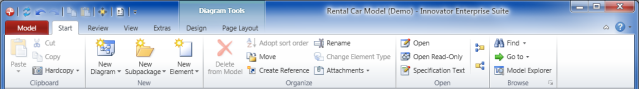
Activate the Design tab from the Diagram Tools context group in the ribbon if this is not the active tab.
This tab contains the Create Diagram Content group.
- Click on the
 actor icon in the Create Diagram Content group in the gallery.
-
Move the mouse over the diagram.
The actor icon is now "attached" to your mouse pointer and follows the movement of the mouse.
-
Click again with the left mouse button where you want the actor to be positioned.
The actor is created and is initially given a default name. You can immediately change this.
Alternative procedure:
- as above
- Click on the actor icon in the Create Diagram Content group in the gallery and keep the left mouse button pressed.
-
Move the mouse with the left mouse button pressed in the diagram.
The actor icon is "attached" to your mouse pointer again and follows the movement of the mouse.
-
Let go of the left mouse button where you want to position the actor.
The actor is created and is initially given a default name. You can immediately change this.
You can create various types of diagram elements in Innovator diagrams in this way. The types of elements available in the diagram editor's gallery primarily depend on the diagram type used, the model template used and the user role selected in a model.
Context
You can create a use case in the same way as an actor (see above).
Alternatively, you can also create a use case by linking it directly with an existing actor. This expresses that this use case is triggered (initiated) by this actor.
How to proceed
-
Select the actor in the diagram.
The selected actor has a blue frame around it. There are various semitransparent icons on the right-hand side; if you hover over them with the mouse they are highlighted – this is called the carousel.
- Select the
 association icon from the carousel and keep the left mouse button pressed.
-
With the left mouse button pressed, drag the icon to a free point in the diagram.
The position of the association that will be created is shown when you drag the icon by a blue rubber band line.
-
Release the left mouse button on a free point in the diagram.
A drop-down list with the partner elements permissible for this type of relationship appears. A
 use case is offered as the only element in the list in this case.
 -
Left mouse click on this entry.
The use case and association to the actor are created; the use case is initially given a default name. You can immediately change this.
You can create various types of different types of connections in Innovator diagrams in this way. The types of elements available in a diagram element's carousel and in the drop-down list primarily depend on the diagram type used, the model template used and the user role selected in a model.
Structuring a System with Classes
Define how a planned system should be structured
How to proceed
-
Activate the Start tab in the ribbon.
This tab contains the New group.
-
Activate the
New Diagram button from the New group.The gallery with templates for new diagrams appears.
-
Select the
 Class Diagram template from the gallery.
An empty class diagram is created and opened in the document area. You can now use this diagram to create classes, interfaces or other classifiers.
You can create various types of diagrams in Innovator models in this way. The types of diagram templates available in the gallery primarily depend on the model template used and the user role selected in a model.
Work in the class diagram you just created for the following steps.
How to proceed
-
Activate the Design tab from the Diagram Tools context group in the ribbon if this is not the active tab.
This tab contains the Create Diagram Content group.
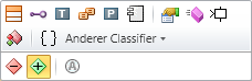
- Select the
 Class icon from the gallery.
-
Move the mouse over the diagram.
The class icon is now "attached" to your mouse pointer and follows the movement of the mouse.
-
Click where you want the class to go with the left mouse button pressed.
The class is created and is initially given a default name. You can immediately change this.
The alternative way of creating an actor (see above) is also possible in this step.
You can create various types of diagram elements in Innovator diagrams in this way. The types of elements available in the diagram editor's gallery primarily depend on the diagram type used, the model template used and the user role selected in a model.
Context
You can create attributes using the class' context menu or the ribbon.
How to proceed
Using the context menu:
-
With the right mouse button, click on the class you want to create the attribute for.
The selected class has a blue frame around it. The context menu for classes in the class diagram appears. The mini toolbar can be found above the context menu:
The colored bar at the top contains icons for commands for creating elements that can be content for the selected class, e.g.
 Attribute,
  Operation or (inner) Class.
 -
Click on the
Attribute icon.The attribute is created within the class and is added to the class' «Attribute» section's content. It is initially given a default name that you can immediately change.
Another way to proceed using the ribbon:
-
Select the class in the diagram with the left mouse button.
The selected class has a blue frame around it.
-
Activate the Design tab from the Diagram Tools context group in the ribbon if this is not the active tab.
This tab contains the Create Diagram Content group.
-
Open the
 Properties submenu in this group.
The submenu contains icons for commands for creating elements that can be content for the selected class, e.g.
Attribute or Operation. -
Click on the
Attribute icon.The attribute is created within the class and is added to the class' «Attribute» section's content. It is initially given a default name that you can immediately change.
If you have already created an attribute in a class, then you can create further attributes quickly by selecting the existing attribute and pressing the [Ctrl]+[+] shortcut keys.
Prerequisites
As described above for attributes, you have created an operation in your class.
Context
The name is not the only deciding factor for an operation, the amount and type of input and output parameters also play a role. You can find out how to edit an operation's entire declaration here.
How to proceed
-
Select the operation in the class with the left mouse button.
The selected operation has a blue frame around it.
-
Select the Edit Declaration command from the operation's context menu or press the shortcut [Ctrl]+[F2].
The dialog for editing the declaration opens. The multi-row editing field initially contains the name of the operation and an empty parameter list, e.g. "
Operation()". -
Between the parentheses, enter the name of the first parameter followed by a colon.
The input help opens and shows all known classifiers in the model in alphabetical order as this parameter's type:
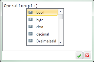
Entering the first few letters shortens the input help to the types that still match step-for-step.
-
Select the type you are searching for in the input help list.
The parameter's type is adopted in the editing field after the colon.
- (Optional) Enter a comma and repeat steps 3 and 4 to define more parameters and their type.
- (Optional) Enter the
outorinoutkeywords in front of the parameter name to define output or input/output parameters. - (Optional) Enter a colon after the closing parenthesis and repeat step 4 to define the operation's return type.
- Click on
 or press the shortcut [Ctrl]+[Enter] in the editing field to adopt the declaration.
Prerequisites
This example assumes that both classes to be linked are already in the diagram. Alternatively, you can create a new class together with the association, as you did when creating use cases (see above).
How to proceed
-
Select the class in the diagram
The selected class has a blue frame around it. There are various semitransparent icons on the right-hand side; if you hover over them with the mouse they are highlighted – this is called the carousel.
- Select the association icon from the carousel and keep the left mouse button pressed.
-
With the left mouse button pressed, drag the icon in the direction of the class to be connected.
The position of the association that will be created is shown when you drag the icon by a blue rubber band line.
-
Let go of the mouse on the class you want to create the association to.
The association is created and initially contains the properties preallocated in the
Association template. You can immediately change these properties using the  Properties tool window or the association's context menu.
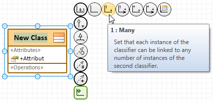
There are predefined templates for many regularly used association types, such as "1:many" or "Aggregation", in which properties such as "Upper and Lower Bound", "Navigability" or "Kind of Aggregation" are already preallocated. You can save yourself the hassle of making changes at a later stage by selecting the suitable template.
Context
Directed relationships are created in the same way as associations (see above); the only difference is that you always have to work from the dependent element to the independent element.
How to proceed
-
Select the class you want to create an inheritance relationship for with the left mouse button.
The selected class has a blue frame around it. The carousel appears on the right-hand side, as was the case in the previous step.
- Select the
 generalization icon from the carousel and keep the left mouse button pressed.
-
With the left mouse button pressed, drag the icon in the direction of the class to be connected.
The position of the inheritance relationship that will be created is shown when you drag the icon by a blue rubber band line.
-
Let go of the mouse on the class your class should inherit from.
The inheritance relationship is created and displayed in the diagram.
Dependency relationships are created in the same way as generalizations, by using one of the arrow icons ( ,
,  ,
,  etc.) in the carousel. You can find out how the dependency relationships differ from each other in the tool tip for the respective arrow icon.
If you have created a directed relationship in the wrong direction by mistake then you can fix this by right-clicking on the incorrect relationship and running the  Revert Direction command in the relationship's context menu.
Showing System Behavior as Activity
Define how the system should realize a planned behavior
Prerequisites
You need to set which class, component or use case a behavior should be specified from before you can create an activity diagram.
How to proceed
- (Optional) Select a BehavioredClassifier (class, component, etc.).
-
Activate the Start tab in the ribbon.
This tab contains the New group.
-
Activate the
New Diagram button from the New group.The gallery with templates for new diagrams appears.
- Select the
 Activity template from the gallery.
- If you omitted step 1, then a selection dialog appears requiring you to select a suitable BehavioredClassifier. Select an existing BehavioredClassifier or use the Create new element button to create a missing BehavioredClassifier. In the latter case, a wizard will then take you through the necessary steps.
If you selected a classifier in step 1 or 5, then a new activity diagram is created and opened in the document area; it initially only contains the activity itself but no details about this activity. You can now use this diagram for displaying individual actions of this activity.
Work in the activity diagram you just created for the following steps.
Context
Actions are the smallest executable element within an activity. This document initially only uses actions of the "Generic Action" type; what should happen to the action is described as text.
How to proceed
-
Activate the Design tab from the Diagram Tools context group in the ribbon if this is not the active tab.
This tab contains the Create Diagram Content group.
- Select the
 Execute Instruction icon from the gallery.
-
Move the mouse in the diagram within the activity's frame.
The action icon is "attached" to your mouse pointer and follows the movement of the mouse. If the mouse pointer is outside of this frame it then changes to an
 icon to show that you cannot create an action outside of the activity.
 -
Click the left mouse button where you want to position the action.
The action is created and is initially shows a default expression. You can immediately change this.
Context
The order of actions is based on the control flow that links the actions with each other.
How to proceed
If the subsequent action already exists in the diagram:
-
Select an action in the diagram.
The selected action has a blue frame around it. There are various semitransparent icons on the right-hand side; if you hover over them with the mouse they are highlighted – this is called the carousel.
- Select the
 control flow edge icon from the carousel and keep the left mouse button pressed.
-
With the left mouse button pressed, drag the icon in the direction of the action to be connected.
The position of the control flow edge that will be created is shown when you drag the icon by a blue rubber band line.
-
Let go of the mouse on the action you want to connect using the control flow edge.
The control flow edge is created. As with almost all model elements, it has a logical name; however, this is not relevant for the modeling and is not visible in the diagram. You can immediately change the properties of the control flow edge using the
Properties tool window or the edge's context menu.
Another way to proceed if the subsequent action does not exist in the diagram yet:
-
Select an action in the diagram.
The selected action has a blue frame around it. There are various semitransparent icons on the right-hand side; if you hover over them with the mouse they are highlighted – this is called the carousel.
- Select the control flow edge icon from the carousel and keep the left mouse button pressed.
-
With the left mouse button pressed, drag the icon to a free point in the diagram.
The position of the control flow edge that will be created is shown when you drag the icon by a blue rubber band line.
-
Release the left mouse button on a free point in the diagram.
A drop-down list with the permissible successors for the selected action appears. The list contains various actions and "Pseudo Nodes" (fork, split etc.).
-
Click with the left mouse button on the entry you want (e.g. on
Execute statement).The action and the control flow edge to this action are created; the action initially has a default text. You can immediately change this.
To show the data object in the diagram
How to proceed
-
Activate the Design tab from the Diagram Tools context group in the ribbon if this is not the active tab.
This tab contains the Create Diagram Content group.
- Select the
 Data Store Node icon from the gallery to show that data should be stored persistently, or select the
  Central Buffer Node icon to show that the data should only be temporarily buffered during execution of the activity.
-
Move the mouse in the diagram within the activity's frame.
The data store or buffer icon is "attached" to your mouse pointer and follows the movement of the mouse. If the mouse pointer is outside of this frame it then changes to an
icon to show that you cannot create a data store/buffer outside of the activity. -
Click the left mouse button where you want to position the node.
The data store/buffer node is created. As the data type has not been specified yet, the node initially only shows the key word
«datastore»or«centralBuffer». You can change the data type directly using the Assign Type tool window, or in the context menu for the data store or buffer node using the Properties command.
Create an object flow from the direction of the writing action to express that a action writes data:
-
Select the writing action in the diagram.
The selected action has a blue frame around it. There are various semitransparent icons on the right-hand side; if you hover over them with the mouse they are highlighted – this is called the carousel.
- Select the
 object flow edge icon from the carousel and keep the left mouse button pressed.
-
With the left mouse button pressed, drag the icon in the direction of the data store/buffer node to be connected.
The position of the object flow edge that will be created is shown when you drag the icon by a blue rubber band line.
-
Release the mouse button over the node that the object flow edge should flow into.
The object flow edge is created. As with almost all model elements, it has a logical name; however, this is not relevant for the modeling and is not visible in the diagram. You can immediately change the properties of the control flow edge using the
Properties tool window or the edge's context menu. An output pin of the same type as the linked data store/buffer node automatically appears for the writing action.
Create an object flow in the direction of the writing action to express that a action reads data:
-
Select the data store/buffer node in the diagram.
The selected node has a blue frame around it. There is a semitransparent icon on the right-hand side; if you hover over it with the mouse it is highlighted – this is called the carousel.
- Select the object flow edge icon from the carousel and keep the left mouse button pressed.
-
With the left mouse button pressed, drag the icon in the direction of the reading action.
The position of the object flow edge that will be created is shown when you drag the icon by a blue rubber band line.
-
Release the mouse button over the action that the object flow edge should flow into.
The object flow edge is created. As with almost all model elements, it has a logical name; however, this is not relevant for the modeling and is not visible in the diagram. You can immediately change the properties of the control flow edge using the
Properties tool window or the edge's context menu. An input pin of the same type as the linked data store/buffer node automatically appears for the reading action.
You can also create both the object flow edge and data store/buffer node diagram elements at the same time by starting the object flow at the action the data will be written from using the "carousel" and releasing the left mouse button on a free point in the diagram.
Prerequisites
(Optional) You have already defined an operation that should be called within your modeled activity within the framework of the "Structuring a System with Classes" topic.
Context
A special action type, a CallBehaviorAction, is used for calling an operation in UML activity diagrams.
How to proceed
-
Activate the Design tab from the Diagram Tools context group in the ribbon if this is not the active tab.
This tab contains the Create Diagram Content group.
- Select the
 Call Operation icon from the gallery.
-
Move the mouse in the diagram within the activity's frame.
As above, the action icon is "attached" to your mouse pointer and follows the movement of the mouse.
-
Click the left mouse button where you want to position the operation call.
The Requirement dialog is opened and contains the operations already defined in your model.
- Select an existing operation or use the Create new element button to create an operation that doesn't yet exist. In the latter case, a wizard will then take you through the necessary steps.
-
Confirm your selection by clicking on the OK button.
The call action is created and labeled with the name of the called operation. A respective input or output pin is automatically created at the call action for each of the operation's parameters.
Another way to proceed by converting an existing action into an operation call:
-
Select the action you want to convert into a call action with the left mouse button.
The selected action has a blue frame around it.
-
Activate the Design tab from the Diagram Tools context group in the ribbon if this is not the active tab.
This tab contains the Model Elements group.
-
Open the
 Refactor submenu in this group and click on the Change Element Type command there.
The wizard for converting model elements is opened.
-
Select the
Call Operation entry in step 1. Click on the Next button to go to step 2.You can set that the action should be converted into an operation in this way. The Requirement dialog is then opened; it contains operations that are already defined in your model.
- In step 2, select an existing operation or use the Create new element button to create an operation that doesn't yet exist. In the latter case, another wizard will then take you through the necessary steps.
-
Confirm your selection by clicking on the OK button.
The wizard for converting model elements is ready for conversion and gives a brief summary of the effects expected by the conversion.
-
Start the conversion by clicking on Finish.
The action is converted into a call action and labeled with the name of the called operation. A respective input or output pin is automatically created at the call action for each of the operation's parameters.
Mapping Flow of Interactions in the System
Define how communication should run within the system
Prerequisites
To be able to create a sequence diagram, you need to set which BehavioredClassifier (normally a class or component) is to describe an interaction.
How to proceed
- (Optional) Select a BehavioredClassifier (class, component, etc.).
-
Activate the Start tab in the ribbon.
This tab contains the New group.
-
Activate the
New Diagram button from the New group.The gallery with templates for new diagrams appears.
- Select the
 interaction template from the gallery.
- If you missed out step 1, a selection dialog appears that requires you to select a suitable BehavioredClassifier. Select an existing BehavioredClassifier or use the Create new element button to create a missing BehavioredClassifier. In the latter case, a wizard will then take you through the necessary steps.
If you selected a classifier in step 1 or 5, then a new sequence diagram is created and opened in the document area; it initially only contains the interaction itself but no details about this interaction. You can now use this diagram for creating communication partners as lifelines and displaying communication between these partners.
Work in the sequence diagram you just created for the following steps.
Prerequisites
The BehavioredClassifier which the interaction belongs to need to be able to be structured by "connectable elements (ConnectableElements)" to be able to define participants for an interaction in a way that makes sense. As actors and use cases classify as BehavioredClassifiers but cannot be structured, only lifelines for the actor or use case as a whole can be created to both these element types in interactions.
Context
Communication partners involved in an interaction are represented in UML sequence diagrams by so-called "lifelines"; they show the chronological sequence of the sent and received messages.
How to proceed
-
Activate the Design tab from the Diagram Tools context group in the ribbon if this is not the active tab.
This tab contains the Create Diagram Content group.
- Select the
 lifeline icon from the gallery.
-
Move the mouse in the diagram within the interaction's frame.
The lifeline icon is "attached" to your mouse pointer and follows the movement of the mouse. If the mouse pointer is outside of this frame it then changes to an
icon to show that you cannot create a lifeline outside of the interaction. -
Click the left mouse button where you want to position the first lifeline.
The Requirement dialog is opened and is initially empty as no interaction partner has been selected.
-
Click on Add....
The Add Prerequisite dialog is opened and contains the interaction's BehavioredClassifier and its ConnectableElements as they are already defined in your model. Select the BehavioredClassifier or one of its ConnectableElements, or use the Create new element button to create a missing ConnectableElement. A wizard then takes you through the steps necessary for this.
-
Confirm your selection by clicking on the OK button.
The selected elements are inserted into the sequence diagram as lifelines next to each other and either labeled with the type of the selected ConnectableElement or with the key word "
self". If the latter is the case, the lifeline represents the BehavioredClassifier of the interaction as a whole. You can immediately modify a lifeline's properties using the Properties tool window.
Context
A so-called signal that contains information to be sent is sent from the sender to the recipient to express that a message is sent in UML sequence diagrams.
How to proceed
-
Left-click to select the vertical (dashed) part of the lifeline from which the message should be sent.
The selected lifeline is shown with a blue selection frame. There are various semitransparent icons on the right-hand side; if you hover over them with the mouse they are highlighted – this is called the carousel.
- Select the
 From Signal... icon from the carousel and keep the left mouse button pressed.
-
With the left mouse button pressed, drag the icon in the direction of the lifeline the message should be sent to.
The position of the message edge that will be created is shown when you drag the icon by a blue rubber band line. If the mouse pointer is not over a lifeline then it changes to an
icon to show that you cannot create a message at this point. -
Let go of the left mouse button over the lifeline you want to send the message to.
The Requirement dialog opens and includes the signals already defined in your model.
- Select an existing signal or use the Create new element button to create a signal which has not yet been defined. In the latter case, a wizard will then take you through the necessary steps.
-
Confirm your selection by clicking on the OK button.
The message edge is created and labeled with the name of the signal sent.
Prerequisites
(Optional) You have already defined an operation that should be called within your modeled interaction within the framework of the "Structuring a System with Classes" topic.
Context
A special message type, known as a (synchronous or asynchronous) OperationCall is used for calling an operation in UML sequence diagrams.
How to proceed
-
Select the vertical (dashed) part of the lifeline which the operation should be called from with the left mouse button.
The selected action has a blue frame around it. There are various semitransparent icons on the right-hand side; if you hover over them with the mouse they are highlighted – this is called the carousel.
- Select the
 Synchronous Call or
  Asynchronous Call icon from the carousel and keep the left mouse button pressed.
-
With the left mouse button pressed, drag the icon toward the lifeline at which an operation is to be called.
The position of the message edge that will be created is shown when you drag the icon by a blue rubber band line. If the mouse pointer is not on a lifeline then it changes to an
icon to show that you cannot create an operation call at this point. -
Let go of the left mouse button over the lifeline you want to send the operation call to.
The Requirement dialog is opened and contains the operations already defined in your model.
- Select an existing operation or use the Create new element button to create an operation that doesn't yet exist. In the latter case, a wizard will then take you through the necessary steps.
-
Confirm your selection by clicking on the OK button.
The operation call is created and labeled with the name of the called operation, including the name of all parameters of this operation.
Creating Specification Texts and Comments
Describing and Commenting on Model Elements
Context
Lots of model elements can have a textual specification to describe a certain aspect of a model element in more detail. Specification texts are primarily used for documenting the model and its model elements.
How to proceed
-
(Optional) Select one or more model elements in the diagram that you want to edit their specification with the left mouse button.
If you have not selected a diagram element, Innovator assumes that the diagram itself should be given a specification.
-
Activate the Design tab from the Diagram Tools context group in the ribbon if this is not the active tab.
This tab contains the Editing group, which contains the
 Specification Text (F3) icon. If this icon is inactive, then you have selected an element that textual specifications cannot be created for.
 -
Click on the
Specification Text (F3) icon.A new window opens for each selected element in the right-hand half of the document area; it shows all available specification texts for this element.
- Enter the text in the respective text definition.
The name of the text definition to be edited is shown in red if your changes have been made.
- Format the text using the Text tab or the context menu.
- Save the text with
 Text>Specification>Save (Ctrl+S).
The name of the edited text definition is shown in black again if the save was successful.
- Close the window with the specifications once you have finished editing.
Context
You can add comments to diagrams to e.g. help other users better understand a diagram.
How to proceed
- (Optional) Select one or more diagram elements that you want to comment on with the left mouse button.
-
Activate the Design tab from the Diagram Tools context group in the ribbon if this is not the active tab.
This tab contains the Create Diagram Content group.
-
Click on the
 Comment icon.
If you selected parts of the diagram in part 1, a comment is created for all selected diagram elements. It initially contains a default text, is positioned in the middle and linked with all selected diagram elements by a dotted line. The comment is placed left above this element if only one diagram element was selected.
You can immediately overwrite the comment's default text with your own comment.
-
If you missed out step 1, move the mouse in the direction of the element you want to comment on.
The comment icon is "attached" to your mouse pointer and follows the movement of the mouse.
-
Click with the left mouse button on the diagram element you want to comment on.
The comment is created for the diagram element you clicked on. It initially contains a default text, is positioned top-left above this element and is linked with this by a dotted line. You can immediately overwrite the comment's text with your own text.
Another way to proceed using the context menu:
- Select one or more diagram elements that you want to make a comment on and right-click to open the context menu for this selection.
-
Click on
 New Comment.
A comment is created for all selected diagram elements. It initially contains a default text, is positioned in the middle and linked with all selected diagram elements by a dotted line. The comment is placed left above this element if only one diagram element was selected.
You can immediately overwrite the comment's default text with your own comment.