Getting Started with Innovator for Database Architects
Get to grips with the essential Innovator for Database Architects functions.
What do you want to do?
| Task | Help topic |
|---|---|
|
Implementing Technical Requirements in an Entity Relationship Model |
|
| Maintaining a Database with an Entity Relationship Model |
 Aligning ER Model and Database Aligning ER Model and Database |
|
Reverse Engineering of an External Database Schema |
|
| Creating a Entity Relationship Model from a Database Schema |
Creating an Initial ER Model from a Database Schema |
|
Describing and Commenting on Model Elements |
Structure of an Entity Relationship Model
Implementing Technical Requirements in an Entity Relationship Model
How to proceed
-
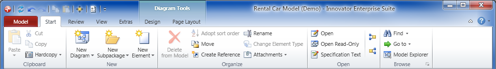
Activate the Start tab in the ribbon.

This tab contains the New group.
-
Activate the
 New Diagram button from the New group.
The gallery with templates for new diagrams appears.
-
Select the
 Entity Relationship Diagram template from the gallery.
An empty entity relationship diagram is created and opened in the document area. You can now use this diagram to create entities and their relationships.
You can create various types of diagrams in Innovator models in this way. The types of diagram templates available in the gallery primarily depend on the model template used and the user role selected in a model.

How to proceed
-
Activate the Design tab from the Diagram Tools context group in the ribbon if this is not the active tab.
This tab contains the Create Diagram Content group.
- Select the
 Entity icon from the Create Diagram Content group in the gallery.
- Drag the icon with the left mouse button pressed onto the diagram.
-
Let go of the mouse button where you want to position the entity.
The entity is created and is initially given a default name.
-
Enter the name and confirm with the [Enter] key.
The selected entity has a blue frame around it. There are various semitransparent icons on the right-hand side; if you hover over them with the mouse they are highlighted – this is called the carousel.
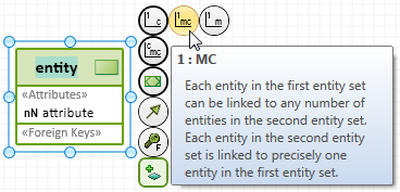
- Select the
 1 : C (relationship) icon from the carousel and keep the left mouse button pressed.
-
With the left mouse button pressed, drag the icon to a free point in the diagram.
The position of the association that will be created is shown when you drag the icon by a blue rubber band line.
-
Release the left mouse button on a free point in the diagram.
A drop-down list with the partner elements permissible for this type of relationship appears. An
entity is the only element shown in the list in this case. -
Left mouse click on this entry.
The entity and the relationship for the entity first created are created; the entity is initially assigned a default name. You can immediately change this.
You can create various types of diagram elements in Innovator diagrams in this way. The types of elements available in the diagram editor's gallery primarily depend on the diagram type used, the model template used and the user role selected in a model.
Context
You can use the table editor for editing an entity's attributes and keys.
You can edit fields with a white background. Fields with a light gray background are read-only fields. Fields with a dark gray background are not defined for the table row's element.
How to proceed
-
Double-click on an entity.
The table editor opens with three tabs: Entity Attribute, Unique Key and Foreign Key.
- Click in the row you want to create a new element below or drag it to the right position using drag-and-drop.
-
Click in the bottom row marked by the
 asterisk.
A corresponding element is created in a new row below the selected row.
-
Click in an editing field in the table.
The field is active.
-
Change the field's value by inputting text or by making a selection from the list of values provided.
The target element's property has been modified.
-
To edit a unique key, double-click on the row marker in front of a unique key.
The table editor for the unique key opens.
-
Click in the bottom row marked by the
asterisk.The Create new using template dialog opens.
-
Select one or more attributes of the entity as part of the key and click on OK.
The selected attributes are part of the key.
Aligning ER Model and Database
Maintaining a Database with an Entity Relationship Model
Mapping requires a corresponding mapping profile. The Database Architect for <database type> model templates each contain a Mapping ER - <database type> mapping profile and support the named database type respectively.
Prerequisites
An engineering action maps a conceptual model to a database schema. Your role needs to have the appropriate configuring privileges to be able to run an engineering action.
Context
You want to map a business ER diagram in a database schema to be able to use this as a basis for a database.
You can initially select the elements (ER diagrams, entities) to be mapped or drag them from the model tree in the mapping window's left-hand area Selection elements.
You can use the Mapping>Map Model>Determine source elements command in the mapping window to specify the resulting source elements from the previous selection elements that would actually be mapped and add them to the selection.
How to proceed
-
Activate the Extras tab from the Diagram Tools context group in the ribbon if this is not the active tab.
This tab contains the Map Model group.
-
Select Extras>Map Model>Mapping.
The configured Mapping Operations are shown in a drop-down list.
-
Select the Map DB schema to ER model mapping process.
The mapping window with the left area for Selection elements and the right area for the Target model appears.
- Drag the ER diagram created at the top from the model tree and drop it in the Selection elements area.
-
Select Mapping>Map Model>Determine source elements.
The engineering action starts and takes some time. A progress window appears. The Calculated Source Elements dialog appears once the calculation has been made.
-
Click on Add to Selection.
The calculated source elements are added to the Selection elements area.
-
Select Mapping>Map Model>Preview.
The engineering action starts and takes some time. A progress window appears. The existing modifications are highlighted in the right-hand area upon simulation.
-
Activate the Mapping>Filter>Show all switch if you want to see more than just the modified elements.
Elements that are not affected by the mapping are also shown.
-
Click on
 Close preview.
The preview is closed.
-
Select Mapping>Map Model>Execute.
The engineering action starts and takes some time. A progress window appears. The mapped elements are shown in the Target model area.
Prerequisites
Engineering actions are used to create DDL scripts. Your role needs to have the appropriate configuring privileges to be able to run an engineering action.
Context
You want to create a database-specific DDL script from a database model to use it in a respective database or align content.
How to proceed
- Select a database model in the model tree.
-
Select Extras>Export>DDL File>Generate Oracle DDL....
The engineering action starts and takes some time. A log appears in the Info tool window for the DDL export which shows you where the script is stored. This is %LOCALAPPDATA%/Temp/ddl/ as standard.
You have created a DDL script.
Prerequisites
You require
- a relational database with the respective login information or
- a DDL file
and
- a model with at least one database schema that contains physical elements, i.e. tables and views.
Context
You can use the comparison to show the differences between physical elements of the relational database or the DDL file and the elements mapped in the database model. The differences are always shown on the left source side. You can use this information to decide which database elements you want to put in your model or which ones you want to update.
How to proceed
- If you want to compare a modeled database schema with the contents of a relational database, then you will connect to the database and import the comparative information.
Select Extras>Import>Relational Database. The Database Import Wizard appears. Enter a new connection in the list of database connections and enter the login information for database access in the Connection and Advanced tabs.
Click on the Advanced import button.
The Database Manager editor is opened.
-
If you wish to compare a modeled database schema with the content of a DDL file, perform a DDL import.
Select Extras>Import>DDL File.
Select the DDL file.
Select a database schema as the target package.
Click on the Advanced import button.
The Database Manager editor is opened.
-
If the target package is not yet preallocated or if you wish to select another schema as target, select this from the drop-down list at the top right in the editor.
All database elements found in the schema are shown in the list on the right-hand side.
- To select a database element you want to show the differences for, activate its check box.
-
To show the differences, select the toggle command Database Connection>Actions>Show differences.
All differences between the selected elements from the DDL file and/or the relational database and the existing database schema in the model determined and visualized in the editor. The differences are shown in the left-hand list of imported elements and in the list of subelements in the bottom area of the editor in a different color and with a tool tip. The Black elements existing in the target schema, the Green elements that do not exist, the Blue elements with different properties and subelements and the deleted Red subelements are shown.
Importing External Database Schema
Reverse engineering of an external database schema by
- Importing the database schema from a connected database or
- Importing a DDL script
Prerequisites
You need a DB schema as the import's target; you can create this as you would an ER diagram (see above).
Context
You need to have set up a connection with a database before you can import a database schema from a database.
How to proceed
-
Select Extras>Import>Relational Database.
The Database Import Wizard appears.
- Click on
 to create a new database connection. Enter the necessary information for making the connection you want.
- If you require special filter or driver settings, then jump to the Advanced tab and make the appropriate settings.
- Click on Check connection settings to test the configured data connection.
-
Click on Next.
A connection is made to the configured database selected in the database connection.
All tables available for import are shown in the wizard.
- Select the tables you want to import in the linked database in the wizard.
- Click on Next.
- Select the database schema in the wizard into which the tables are to be imported.
-
Click on Import.
The selected tables are imported and shown in the DB Managertool window.
Prerequisites
You need a DB schema as the import's target; you can create this as you would an ER diagram (see above).
Context
You can directly import a DDL script.
How to proceed
-
Select Extras>Import>DDL File.
The DDL Import Wizard appears.
- Click on
 and select a DDL file in the dialog.
-
Click on Next.
All tables available for import are shown in the wizard.
- In the DDL, select the tables you want to import in the wizard.
- Click on Next.
- Select the database schema in the wizard into which the tables are to be imported.
-
Click on Import.
The selected tables are imported and shown in the DB Managertool window.
Creating an Initial ER Model from a Database Schema
Creating a Entity Relationship Model from a Database Schema
Prerequisites
An engineering action maps a database schema to a conceptual model. Your role needs to have the appropriate configuring privileges to be able to run an engineering action.
Context
You want to map a database schema in a business ER diagram to be able to use this as a basis for a database.
You can initially select the elements (DB diagrams, tables) to be mapped or drag them from the model tree into the left-hand Selection elements area of the mapping window.
You can use the Mapping>Map Model>Determine source elements command in the mapping window to specify the resulting source elements from the previous selection elements that would actually be mapped and add them to the selection.
How to proceed
-
Activate the Extras tab from the Diagram Tools context group in the ribbon if this is not the active tab.
This tab contains the Map Model group.
-
Select Extras>Map Model>Mapping.
The configured Mapping Operations are shown in a drop-down list.
-
Select the mapping process Map Oracle DB schema to ER model.
The mapping window with the left area for Selection elements and the right area for the Target model appears.
- Drag the DB schema imported above from the model tree and drop it in the Selection elements area.
-
Select Mapping>Map Model>Determine source elements.
The engineering action starts and takes some time. A progress window appears. The Calculated Source Elements dialog appears once the calculation has been made.
-
Click on Add to Selection.
The calculated source elements are added to the Selection elements area.
-
Select Mapping>Map Model>Preview.
The engineering action starts and takes some time. A progress window appears. The existing modifications are highlighted in the right-hand area upon simulation.
-
Activate the Mapping>Filter>Show all switch if you want to see more than just the modified elements.
Elements that are not affected by the mapping are also shown.
-
Click on
Close preview.The preview is closed.
-
Select Mapping>Map Model>Execute.
The engineering action starts and takes some time. A progress window appears. The mapped elements are shown in the Target model area.
Creating Specification Texts and Comments
Describing and Commenting on Model Elements
Context
Lots of model elements can have a textual specification to describe a certain aspect of a model element in more detail. Specification texts are primarily used for documenting the model and its model elements.
How to proceed
-
(Optional) Select one or more model elements in the diagram that you want to edit their specification with the left mouse button.
If you have not selected a diagram element, Innovator assumes that the diagram itself should be given a specification.
-
Activate the Design tab from the Diagram Tools context group in the ribbon if this is not the active tab.
This tab contains the Editing group, which contains the
 Specification Text (F3) icon. If this icon is inactive, then you have selected an element that textual specifications cannot be created for.
 -
Click on the
Specification Text (F3) icon.A new window opens for each selected element in the right-hand half of the document area; it shows all available specification texts for this element.
- Enter the text in the respective text definition.
The name of the text definition to be edited is shown in red if your changes have been made.
- Format the text using the Text tab or the context menu.
- Save the text with
 Text>Specification>Save (Ctrl+S).
The name of the edited text definition is shown in black again if the save was successful.
- Close the window with the specifications once you have finished editing.
Context
You can add comments to diagrams to e.g. help other users better understand a diagram.
How to proceed
- (Optional) Select one or more diagram elements that you want to comment on with the left mouse button.
-
Activate the Design tab from the Diagram Tools context group in the ribbon if this is not the active tab.
This tab contains the Create Diagram Content group.
-
Click on the
 Comment icon.
If you selected parts of the diagram in part 1, a comment is created for all selected diagram elements. It initially contains a default text, is positioned in the middle and linked with all selected diagram elements by a dotted line. The comment is placed left above this element if only one diagram element was selected.
You can immediately overwrite the comment's default text with your own comment.
-
If you missed out step 1, move the mouse in the direction of the element you want to comment on.
The comment icon is "attached" to your mouse pointer and follows the movement of the mouse.
-
Click with the left mouse button on the diagram element you want to comment on.
The comment is created for the diagram element you clicked on. It initially contains a default text, is positioned top-left above this element and is linked with this by a dotted line. You can immediately overwrite the comment's text with your own text.
Another way to proceed using the context menu:
- Select one or more diagram elements that you want to make a comment on and right-click to open the context menu for this selection.
-
Click on
 New Comment.
A comment is created for all selected diagram elements. It initially contains a default text, is positioned in the middle and linked with all selected diagram elements by a dotted line. The comment is placed left above this element if only one diagram element was selected.
You can immediately overwrite the comment's default text with your own comment.