Universally Using Process Maps
Process maps offer a variety of options for clear representation of business processes.
Idea and Implementation
The process map is used above all to represent relationships between activities for business processes. It is a map of the process organization in the company and the basis for developing this further.
You can use a process map to create an overview of your base processes. Graphics are shown as value chains in the process map and help you to visualize how your processes fit together. You can link processes with their organizational structures or IT structures to get an overall view of your company.
Processes in the process map are not identical to BPMN processes. You can link nodes in the process map with various process constructs in the model, e.g. with BPMN processes or BPMN collaborations.
The process map is available in the whiteboard diagram. You can show and hide links to process constructs in the model in the whiteboard.
You can both link existing elements with elements in the process map using drag-and-drop and refine a process with a new element without having to jump to another diagram or the model tree.
Understanding Elements in the Process Map
Process
Processes are the central elements in the process map. They have a special form in the diagram which the value chain graphics are based on. As well as the traditional process arrow, which runs from left to right, there are two other options: management processes point from top to bottom and support processes from bottom to top.
The following diagram shows the Details area of a process in the process map; it was modeled in BPMN at another point in the model. The Details and properties in the Properties tool window can be used to find out what the differences are between a process in the process map and a process in a BPMN diagram.
Figure: Process Map Diagram with Details and Properties Windows
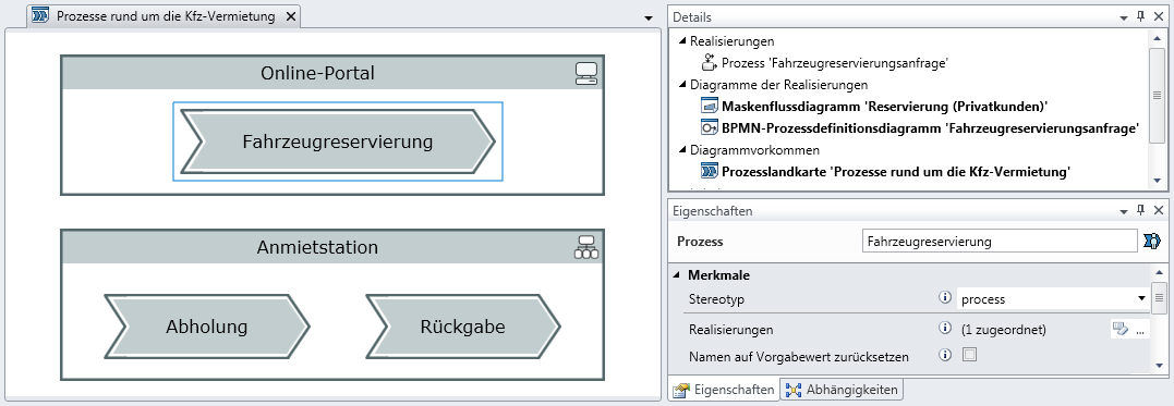
The Car Reservation process is highlighted in the example. It is in the online portal.
What information can you glean from the Details tool window?
- Realization: An element from the process map can be realized by other elements of the model; the realization is a BPMN process in the example shown.
- Diagrams of the Realizations: All diagrams in which the realizing elements occur, i.e. the BPMN process in the example shown. It is used in a mask flow diagram and also has its own BPMN process diagram.
- Diagram Instances: All instances of the process in process maps are listed. It is only in the one process map we just opened in our example.
What can you set in the process' Properties tool window?
- Realizations: You can define the set of elements that apply as realizations of the process in the model. e.g. you can assign multiple process paths that represent scenarios and interpret all of them as possible instances of the car reservation.
- Reset Name to Default Value: This option only appears if your process is realized by precisely one element but the two have different names. Innovator assumes that the realizing element is the leading element: If you change the name of a BPMN process, the name of the process in the process map usually changes as well. If you give the process in the process map another name, this is not automatically aligned. You can use the option to reset the name of the process to the name of the realizing element; Innovator then attempts to maintain both names the same.
These explanations also normally apply for elements which are called at a later stage.
Organizational Unit
Organizational units in the process map are mainly congruent with those from your org chart. If you have already modeled an organization chart, you can drag-and-drop the organizational units modeled there into the process map. An organizational unit that is realized by the organizational unit from the org chart is created and normally has the same name.
IT Element
An IT element in the process map normally represents a larger system, e.g. your online portal or your CRM system.
Why are process units and organizational units not used directly in the process map?
Why does Innovator work with two separate elements that can both represent an organizational unit, with a BPMN process and also with a process in the process map?
The following points should be considered for the separation:
- The process map describes processes with another focus than a BPMN diagram. If you create a "New Customer Acquisition" process in the process map, you may just be identifying a task area for your sales. You do not want to have to decide whether and how the process is to be further modeled in the model when creating the process. The acquisition could be modeled using a collaboration with the customer in BPMN and you could use a process for this or create a global task - this is all irrelevant in the process map.
- You should not feel forced into using BPMN. The process map can also be connected with UML by customizing the model configuration. e.g. if you prefer to model your processes using UML activities, then you can do this.