Creating Relationships to an Element
You can create relationships from an element to a new or existing element in the diagram.
Options for Creating Relationships
Relationships are normally created between model elements in a diagram using the so-called carousel.
It is also possible to edit dependencies between model elements in the Dependencies tool window or in the Dependency Editor.
Standard Case: Carousel
The carousel appears next to the selection rectangle of the diagram element selected. It contains:
-
 circular icons for all the relationships that are permissible for the diagram element selected
 -
 square icons for all types of relationships that may already exist and are not yet shown in the diagram
A connection type always also sets permissible element types that may be created.
If you drag the connection to an existing digram element, then the following may be the target:
- The selected diagram element itself
- Another existing diagram element within or outside of the visible diagram area
- A new element with an owner that may be an existing diagram element within the visible diagram area
If another model element is required when creating a connection, then it is selected in the namespace dialog.
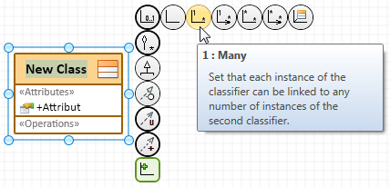
Icons with a thick line around them mean that they contain more than one connection icon; if you place the mouse pointer over it, they expand. A tool tip is normally shown for each connection type.
You can drag the rubber band where you want to create a connection to by clicking and holding on the connection icon. This connection target can also be the selected element itself.
Keep the [Shift] key pressed while releasing the left mouse button to create a connection to an existing diagram element that is not in the visible diagram section. Instead of the list of elements to be created as new, a list of elements that already exist in the diagram appears.
Creation of a connection to an existing diagram element outside of the visible diagram section is limited to direct connections. The Create Connection dialog does not contain existing diagram elements that can be owner of the new target element of the dragged connection type.
The following overview shows the essential variants for creating a relationship to an element. Whether a selection dialog appears or not depends on the connection type (concrete icon) and connection target.
| Variation | Icon Type | Connection Target | Selection Dialog | Description |
|---|---|---|---|---|
| 1 |

|
Free point in the diagram | Always |
Select the target element's element type in the Create Connection dialog. The element types shown are those permitted according to the configuration for the connection type dragged from the selected element in the diagram. A new element is created in the diagram and assigned in the model structure taking any existing creation prerequisites into consideration. The dragged connection is created for the new element; this many create other model element, e.g. roles. |
| 2a |
Selected element or other available diagram element* |
no | The dragged connection is created from the selected element to itself or to the target element; this may create other model elements, e.g. roles. | |
| 2b | yes |
Select the target element's element type in the Create Connection dialog. The element types shown are those permitted according to the configuration for the connection type dragged from the selected element and whose owner may be the selected element or the existing diagram element. Existing connections and elements are shown in the diagram. |
||
| 3 |

|
Other element that has a connection to the selected element that is not yet shown in the diagram | Message | No selection possible. There is no connection of the selected type that already exists and is not yet shown in the diagram. |
| yes |
Select the element that an existing connection t the dragged type should be shown for in the Show in Diagram dialog. The elements offered are those having connections of the dragged type that are not yet shown. For directed relationships, you can evaluate connections existing in the opposite direction. The existing connection and selected element are shown in the diagram. |
* The mouse pointer shows if the selected connection is not permissible for an existing diagram element  .
.
Example for a relationship selection in a selected class' carousel:
Additional Editing Options for Dependencies
A dependency is a relationship between two model elements and represents the fact that when a change is made to the independent model, this will affect the dependent model. The dependency refers to the model elements themselves and not to any instances of these elements which may exist. Depending on the configuration, dependencies can be specified as abstractions, uses, realizations, fulfillment relationships etc..
You can use the Dependencies and Dependency Editor tool windows for editing dependencies.
Creating a Relationship to a New Element with the Carousel
Prerequisites
Diagram exists, is opened and reserved for editing Source element exists.
Context
Creating a relationship to a new element corresponds to variation 1 or 2b in the overview (see above). The diagram itself is the element that can be the owner of the new element in variation 1.
To create a relationship to a new element, drag the respective connection with the mouse button pressed
- To a free point in the diagram or
- To an existing diagram element that can be owner of the new element
The mouse pointer shows if the new element cannot be created at a certain point .
Permissible element types of the new element are shown in the Create Connection dialog.
How to proceed
-
Select the relationship's source element in the diagram.
The carousel appears.
-
Move the mouse pointer over the
connection type you want in the carousel.If the connection type has multiple variations, then expand the respective icons.
-
Drag the connection you want with the mouse button pressed and release the mouse button where you want to place the connection.
The Create Connection dialog appears.
-
Select the element type for the new diagram element.
The namespace dialog appears if another model element that cannot be created from the input selection is required for the process. Select the required element in the model structure or create it in the dialog (Create new element button).
An element of the selected type and the connection to the source element are created. The element is integrated into the model structure. A unique name is created and selected for elements with names.
-
Enter the name of the element and then press the [Enter] key.
The diagram element is renamed. An error message appears if the name entered is not unique.
Creating a Relationship to an Existing Diagram Element with the Carousel
Prerequisites
Diagram exists, is opened and reserved for editing Source element exists.
Context
Creating a relationship to an existing diagram element corresponds to variation 2a in the overview (see above).
To create a relationship to an existing element, drag the respective connection to an existing diagram element with the mouse button pressed. The mouse pointer shows if the selected connection is not permissible for an existing diagram element .
Keep the [Shift] key pressed while releasing the left mouse button at a free point in the diagram area to create a connection to an existing diagram element that is not in the visible diagram section. All elements that already exist in the diagram that can be linked with the source element by the dragged connection type are shown in the Create Connection dialog.
How to proceed
-
Select the relationship's source element in the diagram.
The carousel appears.
-
Move the mouse pointer over the
connection type you want in the carousel.If the connection type has multiple variations, then expand the respective icons.
-
Drag the link with the mouse button pressed to the target element and release the mouse button if the connection target is within the visible diagram section.
The connection between the source and target elements is inserted in the diagram. There are no further steps.
-
Press the [Shift] key and release the mouse button if the connection target is outside of the visible diagram section.
The Create Connection dialog appears.
-
Select the target element you want from the drop-down list.
The connection between the source and target elements is inserted in the diagram.
Adding an Existing Relationship with the Carousel
Prerequisites
Diagram exists, is opened and reserved for editing
A connection of the selected element to an element exists which can be shown in the diagram.
Context
Adding an existing relationship to an element corresponds to variation 3 in the overview (see above).
Drag the corresponding connection with the mouse button pressed to a free point in the diagram to show an existing relationship of the selected element to an element in the diagram.
-
A message appears if there is no connection of the selected type that already exists and is not yet shown in the diagram.
(A previous constraint for the connection icons shown in the carousel is not possible.)
-
The Show in Diagram appears if there is a connection of the selected type that already exists and is not yet shown in the diagram.
Elements with connections of the dragged type that are not yet shown can be chosen from, regardless of whether they are already shown in the diagram or not.
For directed relationships, you can display the elements for which connections to the selected element exist in the opposite direction. To do this, enable the Show in diagram with turned direction check box.
In the Show in Diagram dialog, select the element for which an existing connection of the dragged type should be shown.
How to proceed
-
Within the diagram, select the element for which you want to show an existing relationship in the diagram.
The carousel appears.
-
Move the mouse pointer over the
connection type you want in the carousel.If the connection type has multiple variations, then expand the respective icons.
- Drag the connection to a free point with the mouse button pressed and then release the mouse button.
- A message appears if there is no connection of the selected type that already exists and is not yet shown in the diagram. Confirm the message and select another connection type, if required.
- The Show in Diagram dialog appears if there is a connection of the selected type that already exists and is not yet shown in the diagram. The elements offered are those having connections of the dragged type that are not yet shown. In order to be able to evaluate the connections existing in the opposite direction for directed relationships, activate the Show in diagram with turned direction check box.
- Select the element for which you want to show an existing relationship in the diagram.
-
Confirm with OK.
The existing relationship for the selected element is shown in the diagram. If the element selected in the Show in Diagram dialog is not yet shown in the diagram, it is shown in the diagram at the position of the mouse pointer.