Getting Started with Innovator for Business Analysts
Get to grips with the most important Innovator for Business Analyst functions.
What do you want to do?
| Task | Help Topic |
|---|---|
| Model a flow of worksteps |
 Modeling Processes Modeling Processes |
| Modeling Organizational Units and Their Hierarchical Relationships |
Modeling Hierarchy of Organizational Units |
| Model decisions and their logic |
Modeling Decisions |
| Describe and comment on model elements |
Creating Specification Texts and Comments |
Modeling Processes
Setting a Flow of Worksteps
How to proceed
-
Activate the Start tab in the ribbon.
This tab contains the New group.
-
Activate the
 New Element button from the New group.
A menu with templates for new elements appears.
-
Select the
 Process template from the process sub group in the menu.
A process diagram is created and opened in the document area. If Innovator initially asks you to select an owner for the process, then you should select the Processes and Collaborations package (folder).
The process diagram has a frame for the process and the steps involved in it. Rename the process by selecting the name field and entering a new name.

How to proceed
-
Activate the Design tab in the ribbon if this is not the active tab.
This tab contains the Create Diagram Content group.
-
Drag the
 Result icon from the gallery with the left mouse button pressed to a free point in the process.
 -
Let go of the mouse where you want to position the start event.
The event is created without a name to start with. You can change the name straight away.
Tip
You can create various types of diagram elements in Innovator diagrams in this way. The types of elements available in the diagram editor's gallery primarily depend on the diagram type used, the model template used and the user role selected in a model.
How to proceed
-
Select the event you just created.
There are two connection icons to the right of the event in the carousel: the sequence flow and the data association.
-
Select the sequence flow, hold the left mouse button pressed and drag the sequence flow to where you want to create a task.
-
Release the mouse button.
A list of elements that you can create as the sequence flow's target appears.
-
Select the
 task from the list.
A new task including a sequence flow between the start event and the task is created. You can change the name of the task straight away.
How to proceed
-
Select the task you just created.
As before, there are two connection icons to the right of the task in the carousel: the sequence flow and the data association.
-
Select the sequence flow, keep the left mouse button pressed and press the [Ctrl] key at the same time; drag the sequence flow over the right or bottom edge of the process frame. You will see that the process automatically changes size and the process then grows to fit where you want it.
-
Release the mouse button.
A list of elements that you can create as the sequence flow's target appears.
-
Select the
task from the list.A new task including a sequence flow between the start event and the task is created. You can change the name of the task straight away.
How to proceed
-
To make room for the new element, move the mouse pointer to the position above or below the sequence flow where you want to insert the gateway; press and hold down the right mouse button and move the mouse to the right.
All elements to the right of the mouse pointer are moved.
-
Activate the Design tab in the ribbon if this is not the active tab.
This tab contains the Create Diagram Content group.
-
Select the
 Gateway icon from the gallery.
 -
With the left mouse button pressed, drag the icon to the sequence flow in which you want to insert the gateway; release the mouse button when the sequence flow is highlighted.
The sequence flow is split and the gateway is set between both sequence flows. You can now create further sequence flows with subsequent elements on the gateway.
How to proceed
-
You can normally use an element's context menu to quickly jump between the available element types; for a gateway e.g. between an exclusive OR and an AND, i.e. a fork.
-
Open the gateway's context menu.
The mini toolbar with all permitted gateway types is situated above or below the context menu:

-
Select the
 icon which represents an exclusive gateway.
Your gateway immediately becomes an exclusive gateway.
How to proceed
-
Activate the Design tab in the ribbon if this is not the active tab.
This tab contains the Create Diagram Content group.
-
With the left mouse button pressed, drag the
 Time (event definition) icon to the start event you just created; release the mouse button when the start event is highlighted.
The event has an event definition that can be used throughout the model. You can change the name of the event definition straight away. You have now created a timer event definition, i.e. you have modeled that your process starts as soon as the timer event begins.
How to proceed
-
Activate the Design tab from the Diagram Tools context group if this is not the active tab.
This tab contains the Create Diagram Content group.
-
With the left mouse button pressed, drag the
 Horizontal Process icon to the task you just created; release the mouse button when the task is highlighted.
A new process is created. The task becomes the call activity of the newly-created process. A
 on the task shows that a process is stored.
 -
Open the Go to submenu in the task's context menu to jump to the newly created process. The last entry in the menu shows the diagram you can define the process in. Select the bottom-most entry.
The diagram for the newly-created process is opened. The process diagram has a frame for the process and the steps involved in it.
How to proceed
-
Activate the Design tab in the ribbon if this is not the active tab.
This tab contains the Create Diagram Content group.
-
With the left mouse button pressed, drag the
 Lane icon from the gallery to the process area and release the mouse button.
A first lane is created directly below the process. We will now create a second lane as you will often want to be able to split a process' tasks into various areas.
-
Drag another
Lane from the gallery into the process or via the existing lane, keeping the left mouse button pressed.You will see three arrows that enable you to insert the new lane corresponding to the arrow direction. You can superordinate the lane or insert it above or below the existing lane.
-
Hold the left mouse button down and go with your mouse pointer to the arrow pointing up and release the mouse button.
The new lane is inserted directly above the lane that was just created. If you did not select any of the arrows, then the new lane is added below the highlighted lane and there is a hierarchy between the lanes.
Modeling Hierarchy of Organizational Units
Defining which Organizational Units are Relevant for the Process Model
How to proceed
-
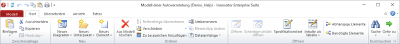
Activate the Start tab in the ribbon.
This tab contains the New Diagram group.
-
Activate the
 New Diagram button from the New group.
The gallery with templates for new diagrams appears.
-
Select the
 Organizational Chart template from the gallery.
An organizational chart is created and opened in the document area. You can use this diagram for creating organizational units, positions and employees and link them with each other.
Tip
You can create various types of diagrams in Innovator models in this way. The types of diagram templates available in the gallery primarily depend on the model template used and the user role selected in a model.
How to proceed
-
Activate the Design tab in the ribbon if this is not the active tab.
This tab contains the Create Diagram Content group.
-
Select the
 Organizational Unit icon from the gallery
 -
Drag the icon with the left mouse button pressed to a free point in the diagram.
-
Let go of the mouse where you want to position the element.
The organizational unit is created. You can change the name straight away.
How to proceed
-
Select the organizational unit just created. You should now see a connection icon for a hierarchical subordination to the right.
-
Select the subordination, hold the left mouse button pressed and drag the subordinate relationship where you want to create a position.
-
Release the mouse button.
A list of elements that you can create as the hierarchical subordination's target appears.
-
Select the
 Position from the list.
A new position is created below the organizational unit. You can now change the name of the position.
Modeling Decisions
Display requirements and rules for recurring decisions
How to proceed
-
Activate the Start tab in the ribbon.
This tab contains the New Diagram group.
-
Activate the
New Diagram button from the New group.The gallery with templates for new diagrams appears.
-
Select the
 Decision Requirements Diagramtemplate from the gallery.
A Decision Requirements Diagram is created and opened in the document area. You can use this diagram for creating decisions, business knowledges, information, information sources and decision services and link them with each other.
Tip
You can create various types of diagrams in Innovator models in this way. The types of diagram templates available in the gallery primarily depend on the model template used and the user role selected in a model.
How to proceed
-
Activate the Design tab in the ribbon if this is not the active tab.
This tab contains the Create Diagram Content group.
-
Select the
 Decision icon from the gallery.
 -
Drag the icon with the left mouse button pressed to a free point in the diagram.
-
Let go of the mouse where you want to position the element.
The Decision is created. You can change the name straight away.
Context
You can create a Business Knowledge Model in the same way as a Decision (see above).
Alternatively, you can also create a Business Knowledge Model by linking it directly with an existing Decision. This shows that this Business Knowledge Model is requested by this Decision.
How to proceed
-
Select the Decision in the diagram.
The selected Decision is shown with a blue selection frame. There are various semitransparent icons on the right-hand side that are highlighted if you hover the mouse over them – this is called the carousel.
-
Select the
 Knowledge Requirement icon from the carousel and keep the left mouse button pressed.
 -
With the left mouse button pressed, drag the icon to a free point in the diagram.
When dragging, the position of the Knowledge Requirement that will be created is indicated by a blue rubber band line.
-
Release the left mouse button on a free point in the diagram.
A drop-down list with the partner elements permissible for this type of relationship appears. A
 Decision Service and
  Business Knowledge Model are offered as elements in the list.
 -
Left mouse click on the
Business Knowledge Model entry.The Decision's Business Knowledge Model and Knowledge Requirement are created; the Business Knowledge Model is initially given a default name. You can immediately change this.
Tip
You can create various kinds of different connection types in Innovator diagrams in this way. The types of elements available in a diagram element's carousel and in the drop-down list primarily depend on the diagram type used, the model template used and the user role selected in a model.
Context
The Input Data DMN element provides structured data for a decision. It is e.g. linked to the Variable Type Structure Definition for this.
DMN test data is also linked to it so that you can simulate decisions.
How to proceed
-
Select the Decision just created. You should now see a connection icon for an
 Information Requirement to the right.
 -
Select the Information Requirement, hold the left mouse button pressed and drag the Input Data where you want to create a position.
-
Release the mouse button.
A list of elements that you can create as the Information Requirement's target appears.
-
Select the
 Input Data from the list.
An Input Data is created. You can now change the name of the Input Data.
Context
Information requires a type. FEEL primitive types can be used, such as e.g. "number", "string" and "boolean". You can find these in the FEEL Types namespace.
You can implement complex data types using structure definitions. To do this, create a structure definition with entries. Their types can be FEEL primitive types or other structure definitions.
How to proceed
-
Select the Decision just created.
-
Click on
 in the Properties tool window for the Variable Type property.
The Determine variable type for Input Data '0' dialog appears.
-
To assign a Structure Definition, click on the structure element with the structure definitions to the left in the tree, select the type on the right and confirm with OK.
The type is assigned Decision.
Context
Use a base element Context if you want to create a single element and flexibly design the structure. You can use Context blocks to group logical elements that belong together.
You can type context entries using the Set Type context menu in the Determine type for '0' element dialog.
How to proceed
-
Double-click on the Decision you previously created.
The table editor for boxed expressions opens.
-
Click with the right mouse button in the Empty Expression block and select the
 Context in the context menu.
A Context block is created.
-
Click with the right mouse button in the context's Empty Expression block and select the
Context again in the context menu.A Context block in the Context block above is created.
-
Click with the right mouse button in the entry block and select the
 Context Entry (Ctrl+OemPlus) in the context menu.
The Context Entry is created. You can create the decision logic structure in this way.
-
Click with the right mouse button in the Empty Expression block of the context entry and select the
 Function Definition (FEEL) in the context menu.
A Function Definition is created.
-
Click with the right mouse button in the () function block and select Modify (F2).
The Edit Function Parameters dialog appears.
-
To create a function parameter, click on Create.
A parameter is created and can be edited.
-
To type a function parameter, click on Set Type....
The Determine type for '0' element dialog appears.
-
To assign a FEEL type, click on FEEL Types in the tree, select the type on the right and confirm with OK.
The type is assigned to the parameter.
-
Repeat from step 7 for further function parameters if required.
Close parameter editing by clicking on Close.
You have now created a FEEL function definition with typed parameters within a context structure.
Creating Specification Texts and Comments
Describe and comment on model elements
Context
Lots of model elements can have a textual specification to describe a certain aspect of a model element in more detail. Specification texts are primarily used for documenting the model and its model elements.
How to proceed
-
(Optional) Select one or more model elements in the diagram that you want to edit their specification with the left mouse button.
If you have not selected a diagram element, Innovator assumes that the diagram itself should be given a specification.
-
Activate the Design tab in the ribbon if this is not the active tab.
This tab contains the Edit group, which contains the
 Specification (F3) icon. If this icon is inactive, then you have selected an element that textual specifications cannot be created for.
 -
Click on the
Specification (F3) icon.A new window opens for each selected element in the right-hand half of the document area; it shows all available specification texts for this element.
-
Enter the text in the respective text definition.
The name of the text definition to be edited is shown in red if your changes have been made.
-
Format the text using the Text tab or the context menu.
-
Close the text with
 Text>Specification>Save (Ctrl+S).
The name of the edited text definition is shown in black again if the save was successful.
-
Close the window with the specification texts once you have finished editing.
Context
You can add comments to diagrams to e.g. help other users better understand a diagram.
How to proceed
-
(Optional) Select one or more diagram elements that you want to comment on with [Ctrl] and the left mouse button.
-
Activate the Design tab in the ribbon if this is not the active tab.
This tab contains the Create Diagram Content group.
-
Click on the
 Comment icon.
If you selected parts of the diagram in part 1, a comment is created for all selected diagram elements. It initially contains a default text, is positioned in the middle and linked with all selected diagram elements by a dotted line. The comment is placed left above this element if only one diagram element was selected.
-
If you missed out step 1, move the mouse in the direction of the element you want to comment on.
The comment icon is "attached" to your mouse pointer and follows the movement of the mouse.
-
Click with the left mouse button on the diagram element you want to comment on.
The comment is created for the diagram element you clicked on. It initially contains a default text, is positioned top-left above this element and is linked with this by a dotted line.
-
Overwrite the default comment text directly with your own comment. Use the [Enter] key for hard returns.
-
To finish the comment, click on [Ctrl]+[Enter] or [(Nicht definierte Variable:UIVar_Menu.KeyTab)].
Another way to proceed using the context menu:
-
Select one or more diagram elements that you want to make a comment for and press the right mouse button to open the context menu for this selection.
-
Click on
 New Comment.
A comment is created for all selected diagram elements. It initially contains a default text, is positioned in the middle and linked with all selected diagram elements by a dotted line. The comment is placed left above this element if only one diagram element was selected.
-
Overwrite the default comment text directly with your own comment. Use the [Enter] key for hard returns.
-
To finish the comment, click on [Ctrl]+[Enter] or [(Nicht definierte Variable:UIVar_Menu.KeyTab)].
